This thread has been locked.

If you have a related question, please click the "Ask a related question" button in the top right corner. The newly created question will be automatically linked to this question.

TLV320DAC3203EVM-K: hardware set up for external I2S signals

Guru 29700 points
Part Number: TLV320DAC3203EVM-K

Hi Team,

My customer considers to use TLV320DAC3203EVM-K + USB-MODEVM.
He wants to evaluate it with external I2S signals from another board.
Is it possible?
I would like to know hardware settings to achieve it.

Best Regards,
Yaita

  • Hi, Yaita-san,

    The application is possible. The TLV320DAC3203EVM-K has many functionalities and it can be configured in multiple ways. In addition, the TLV320DAC3203EVM-K GUI has preconfigured codes that you may use in order to connect I2S signals from PC or even from another board.

    I attached an example code for details.

    High_Performance_Stereo_Playback.txt
    ###############################################
    # High Performance Stereo Playback
    # ---------------------------------------------
    # PowerTune mode PTM_P3 is used for high
    # performance 16-bit audio. 
    #
    # Audio is routed to headphone outputs.
    ###############################################


    ###############################################
    # Software Reset
    ###############################################
    #
    # Select Page 0
    w 30 00 00
    #
    # Initialize the device through software reset
    w 30 01 01
    #
    ###############################################


    ###############################################
    # Clock Settings
    # ---------------------------------------------
    # The codec receives: MCLK = 11.2896 MHz,
    # BLCK = 2.8224 MHz, WCLK = 44.1 kHz
    ###############################################
    #
    # Select Page 0
    w 30 00 00
    #
    # NDAC = 1, MDAC = 2
    w 30 0b 81 82
    #
    ###############################################


    ###############################################
    # Signal Processing Settings
    ###############################################
    #
    # Select Page 0
    w 30 00 00
    #
    # Set the DAC Mode to PRB_P8
    w 30 3c 08
    #
    ###############################################


    ###############################################
    # Configure Power Supplies
    ###############################################
    #
    # Select Page 1
    w 30 00 01
    #
    # Disable weak AVDD to DVDD connection
    w 30 01 08
    #
    # Enable Master Analog Power Control
    w 30 02 00
    #
    # Set the input power-up time to 3.1ms
    w 30 47 32
    #
    # Set the REF charging time to 40ms
    w 30 7b 01
    #
    ###############################################


    ###############################################
    # Configure DAC Channel
    ###############################################
    #
    # Select Page 1
    w 30 00 01
    #
    # De-pop: 5 time constants, 6k resistance
    w 30 14 25
    #
    # Route LDAC/RDAC to HPL/HPR
    w 30 0c 08 08
    #
    # Select Page 0
    w 30 00 00
    #
    # DAC => 0dB
    w 30 41 00 00
    #
    # Power up LDAC/RDAC
    w 30 3f d6
    #
    # Select Page 1
    w 30 00 01
    #
    # Unmute HPL/HPR driver, 0dB Gain
    w 30 10 00 00
    #
    # Power up HPL/HPR
    w 30 09 30
    #
    # Select Page 0
    w 30 00 00
    #
    # Unmute LDAC/RDAC
    w 30 40 00
    #
    ###############################################

    I hope this helps. Please let me know if you have additional questions or comments.

    Best regards,
    Luis Fernando Rodríguez S.

  • Hi Luis-san,

    Thank you for your reply.
    Could you tell me hardware settings with external I2S signals from another board?
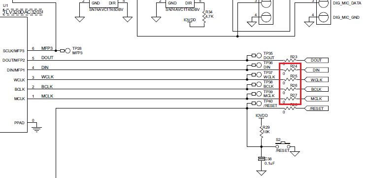
    I believe R24~R27 should be removed then apply external I2S signals to TP36~TP39.
    Is my understanding correct?


    Best Regards,
    Yaita

  • Hi, Yaita-san,

    There's no need to remove the 0-ohm resistors. I would recommend the following procedure:

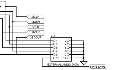
    1.- Disable the I2S and MCLK signals from the USB port with the help of SW2 4-5. This will avoid collision in the I2S lines if external clock signals are connected. 

     2.- Connect the external clock signals to J14 as shown in the following diagram:

    3.- Enable the external clock signals and verify its operation with the help of a scope on the clock test points of the EVM (TP35 - TP39).

    Please try it and let me know if you have questions or comments about this.

    Best regards,
    Luis Fernando Rodríguez S.

  • Hi Luis-san,

    Thank you always for your kind support!
    I will have my customer try as you suggested. 

    Best Regards,
    Yaita