This thread has been locked.

If you have a related question, please click the "Ask a related question" button in the top right corner. The newly created question will be automatically linked to this question.

DRV134: DRV134

Part Number: DRV134
Other Parts Discussed in Thread: INA134, LM337, PGA2320, OPA1641, OPA172, OPA1652

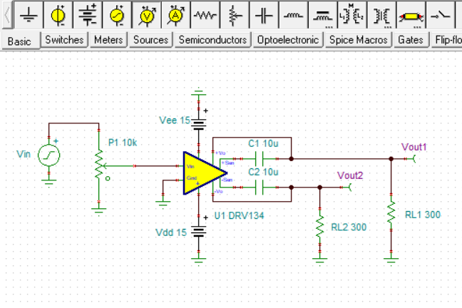
Hi there / i wander if i can use the DRV 134 after the INA 134 without a buffer between them. the INA134 receiver to convert balance signal into unbalance, then to ed just the volume for my needs, and then bring it back to balance with the DRV134.

Thank you in advance

ilan  

  • Hi Ilian,

    The INA134 output voltage swing is rated with a 2 kilohm load, while the DRV134 has an input resistance of 10 kilohms. Therefore, it looks like the INA134 can directly drive the DRV134 without having to add a buffer.

    I am not sure exactly how you are going to configure the volume adjustment circuit between them. That needs to be considered so that you don't load the INA134 output to heavily.

    Regards, Thomas
    Precision Amplifiers Applications Engineering
  • Hi - thank you - I adjust the volume simply with 10kohm log potentiometer, is it ok?
  • Hi Ilian,

    The lowest load resistance that the INA134 will see when the potentiometer is adjusted is 5 kilohms, which is less than the 2 kilohm test load. It should be okay.

    Regards, Thomas
    Precision Amplifiers Applications Engineering
  • Thank for that information. Another question that related to a noises of hum in the woofer and high frequencies in the tweeter when I send my signal into a sensitive class D amplifier with a passive speakers. Could it be due to an inaccurate voltage level of the +/- power supply. I use 7815 and 7915 regulators for my power supply. Should I use LM337 and LM333 instead? Or the noises are from an unsymmetrical CMRR output summing of the DRV134?
  • Hello Ilian,

    Well, it looks like you need to narrow down where the noise appears in the signal chain. If you don't hear it at the DRV134 output, then it must be occurring in the class D amplifier circuit that follow the DRV. It certainly appears that the regulators must readily provide the peak current required by the class D amplifiers. I don't work directly with the regulator products so I am not expert with which ones may be best for your application.

    We don't cover class D amplifier in the Precision Amplifiers group, but assisted with your inquiry because we do provide coverage for the INA134 and DRV134. I suggest closing this e2e inquiry and then opening a new one in the Audio e2e forum, then explain the noise issues you are observing. If you are using a TI class D amplifier product it is much more likely that they will be able to assist you with the issue.

    Regards, Thomas

    Precision Amplifiers Applications Engineering

  • "Hi - thank you - I adjust the volume simply with 10kohm log potentiometer, is it ok?"

    All due respect to Thomas, but it's not OK. You must drive the input of the DRV134 with a low impedance. Driving it directly from a pot's wiper will make the output balance go all to hell, and worse, that imbalance will be a function of the pot position.

    You must put a buffer op-amp between your pot's wiper and the DRV134 input if you want it to work correctly.
  • Hi Andy,

    Thank you for your interest in the DRV134 topic and commenting on it. Certainly, if the highest performance is needed adding a buffer makes things easier. I suppose it comes down to just what level of output balance performance that is required and if the buffer must be included.

    When I had ran some TINA simulations on the DRV134 circuit without including the buffer and adjusted the 10 k potentiometer for different percentage of resistance settings, the output levels from the two outputs were very close to each other for each potentiometer setting. You can see the simulation results here:


    The 10 k input resistance of the DRV134 loads the potentiometer wiper resistance to ground and gain doesn't correspond exactly with the percent setting. But otherwise, the output levels relative to each other are very similar. When I add a buffer in between the potentiometer and the DRV134 input, the gain is correct with the percentage setting, and the output level are again very similar. It may be the small imbalance in output levels that would be an issue.

    If you have deeper insight into output balance problems caused by using this approach please share the information with us. Sharing helps build the knowledge basis and we all can learn.

    Regards, Thomas

    Precision Amplifiers Applications Engineering

  • Hello Ilian,

    After some off the forum discussion with Kai, one of our very frequent contributors to the Precision Amplifiers e2e, I now recognize the circuit performance concern that Andy brought up. He is correct, adding the potentiometer directly at the DRV134 input without a buffer will severely degrade the common-mode rejection performance normally achieved at the DRV134 outputs. Common-mode noise and hum rejection would be very poor without buffering the DRV134 input from the high potentiometer resistance added to the input.

    Kai provided me with two images from TINA simulations that illustrate the DRV134 common-mode degradation issue. Using them its is easy to see the effect of a common-mode signal acting on the outputs, with and without the potentiometer connected at the DRV134 input.

    Directly below is the performance of the DRV134 circuit without the potentiometer. VG1 is a common-mode signal driving the grounds of the two output loads RL1 and RL2. The differential output voltage (VM1) is ideally zero and that is what the output plot indicates:

    Here differential output is shown with the input potentiometer included and set to 50 %. The common-mode signal now affects the differential output, indicating the common-mode rejection has been compromised:

    This result verifies that adding the potentiometer directly to the DRV134 input degrades the normally high common-mode rejection. This outcome is the result of misbalancing the precisely set internal stage gains needed for high common-mode rejection. Therefore, a buffer amplifier must be used in between the potentiometer and the DRV134 if the output common mode performance is to be preserved.

    Thanks to Andy and Kai for their assistance and providing insight into this issue.

    Regards, Thomas

    Precision Amplifiers Applications Engineering

  • Hi, Thomas -- thanks for taking the time to verify all of this.

    The concern about the low-ish input impedance of the DRV134 was noted on one of the pro-audio design forums I used to read. I recently did a design which used the DRV134 for the outputs stages (four stereo pairs) and three of those pairs were driven by op-amp outputs (actually from PGA2320) and the fourth was connected to the outputs of analog muxes which had enough on-resistance to bork the DRV134's output balance. It was just an oversight, something I didn't pay enough attention to, but this was the first time I made that mistake and the results were clear (and ugly).
  • Thanks to all of you for the very helpful information. I have another two questions related to the topic:
    1- In the datasheet of the DRV134 and INA134 you suggest to use 1uf capacitors between ground and +/- Vcc/Vee. Isn’t it better to use smaller size of ceramic capacitor such as 100pf?
    2- What is the function of the 300 ohm resistors at the outputs of the DRV134 (RL1, RL2)?
    Thanks you in advance
    Ilan
  • Hi Andy,

    Thanks much for relating your experience with the DRV134. The information should prove helpful to others considering similar applications for the DRV134.

    Regards, Thomas
    Precision Amplifiers Applications Engineering
  • Hi Ilian,

    1- In the datasheet of the DRV134 and INA134 you suggest to use 1uf capacitors between ground and +/- Vcc/Vee. Isn’t it better to use smaller size of ceramic capacitor such as 100pf?

    The power supply bypass capacitors should exhibit a very low impedance in the operating frequency range, in this case the audio frequency range. The low impedance shunts ac and noise riding on the dc power supply level reducing their level. The large bypass capacitor serves as a charge reservoir during intended transient output events when the DRV134 needs to very quickly supply current to a load.

    A 100 pF capacitor has about 1.5 Megohms of capacitive reactance at 1 kHz so it is not an effective bypass in the audio frequency range.

    2- What is the function of the 300 ohm resistors at the outputs of the DRV134 (RL1, RL2)?

    The 300 ohm resistors were in the original TINA TI Reference Design circuit. They also are used in datasheet Figure 25, the Output Common-Mode Rejection Test Circuit, so I left them in for the simulation. It doesn't mean they are necessarily needed for all applicaitons.

    The DRV134 datasheet shows R1 (RL1), R2 (RL2) and a differential RL being applied in the various circuits. The DRV134 outputs can drive a 600 Ohm load to 17 VRMS and that is an important point. Figure 29, a Complete Audio Driver and Receiver Circuit, doesn't include the load resistors and simply drives a twisted pair line connected to the input of INA134 receiver. When driving very long cables have a characteristic impedance of 600 Ohms it may be beneficial to terminate the line in a 600 Ohm load, and the DRV134 can deliver the current.

    An important point about including, or not including the resistors in the circuit can be observed by viewing the THD + noise (%) graphs in datasheet section 7.4. The curves on the graphs indicate that without the load resistors the THD + noise (%) is highest above 1 kHz compared to when they are present in some form. Adding a 600 Ohm resistor from each output to ground improves the THD + noise compared to when they are not used. And the best THD + noise is obtained when the 600 Ohm differential load resistor is used alone. Therefore, the THD + noise performance is an important factor in determining their use.

    Regards, Thomas

    Precision Amplifiers Applications Engineering 

  • Thank you, what OP buffer could feet to work smoothly with the ina134 and the drv134?

    Thank you ' ilan


  • Hi Ilian,

    Here are links to two of our SoundPlus audio op amps, and one industrial op amp that should provide very good audio performances in your application. Note that the OPA1652 is a dual op amp and you may not need the extra channel. Both the OPA1641 and the OPA172 are single channel op amps.

    www.ti.com/.../OPA1652

    www.ti.com/.../OPA1641

    www.ti.com/.../OPA172

    Regards, Thomas
    Precision Amplifiers Applications Engineering