This thread has been locked.
If you have a related question, please click the "Ask a related question" button in the top right corner. The newly created question will be automatically linked to this question.
1. Mute circuit - If the idea is to unmute after a time interval, then Cm will do exactly the opposite, right? It will be discharged initially and then create a current rush when powered on. Shold it not be connected to Pin 7 and not ground to work as advertised?
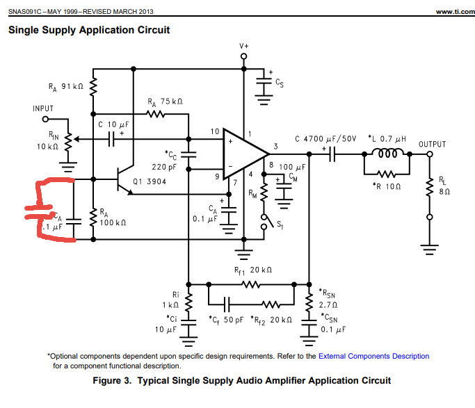
2. The circuit will exhibit quite a lot of (mainly 2nd order) distortion at low frequencies because of the Vcc/2 circuit, Ra, Ra, Ca. Putting a 100uF cap from Pin7 to ground helps somewhat, but parallelling Ca with 100uF lowers that distortion by a factor 10 as the capacitor value in that case is multiplied by the Hfe of Q1. Filtering there will also help getting a cleaner bias through Ra
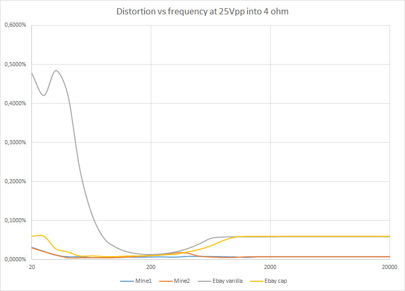
Graph below shows measurements taken with a HP8903A on two PCBs. "Mine" is one that I did, following the ideas in the DiyAudio thread where Tom Christensen (Neurochrome) provided some excellent advice. The other PCB is a cheap one I got from eBay for prototyping. Vanilla is as is (schematic on page 6 of datasheet) and "ebay cap" is the same but with 100uF across Ca. The difference is quite big.
I used a single-supply because I wanted an SMPS, because the amp will sit in a small loudspeaker box on a pedestal and I wanted to keep the weight down.
Any comments??
The schematic is straight from the LM3886 datasheet, page 6:
My capacitor added in red. The measurements were taken with a lab power supply. A good SMPS can provide stable and noiseless power as well and at the fraction of the weight of a linear PSU. In this case it is a tradeoff. I need low weight and SMPSes with dual outputs, say +/- 18V are extremely rare.
So, yes, a single supply has it's tradeoffs, but there is no reason not to try to get the best possible result. The amp provides quite respectable values for THD with this simple modification.
Thanks, but it does not really answer my question. I know how the mute circuit is supposed to work, but from my understanding does not the mute circuit in the single-supply schematic not work as intended.
Hi Anders,
1. Grounding CM at pin 7 of LM3886 instead of pin 4 in the single supply circuit should work. The only disadvantage I see is, that Q1 must deliver a more abrupt current change when de-muting. Especially in combination with a small CA this could cause an audible click. Here, the conventional circuit with the smooth current change:
And here, your circuit with the more abrupt current change:
2. Increasing CA looks like a good idea when it comes to distortion and PSRR. But a big CA increases the time pin 7 needs to settle to the final value during power-up. Me thinks, that the designers of this chip wanted to keep this period short. This might be the reason why CA look so small. A fast settling time seems to be the more important the higher the supply voltage is, because this means a higher stress to the internal circuitry which is directly referenced to pin 7.
Kai
Thanks for taking the time to simulate this. I did the same a while back and remember I do not have a mute switch, all I want is mute when powering on and off. Here is my schematic with Cm (C3 here) connected to Vcc/2:
And accompanying current out of the mute pin when power is applied:
It could be that the tradeoff you mention is why Ca is that small
If I bring Cm to ground, then it looks like this:
What am I missing?