


Other Parts Discussed in Thread: PGA2500,
Hi Sirs,
My customer got noise problem with 6.81kR, 1% resistors with Phantom circuit as the below picture, while the noise problem could be improved by replacing high precision 6.81kR, 0.1% resistors. How can we explain this investigate in theory?
Would you please provide tips how to modify the reference design if we need to keep using 1% resistors? 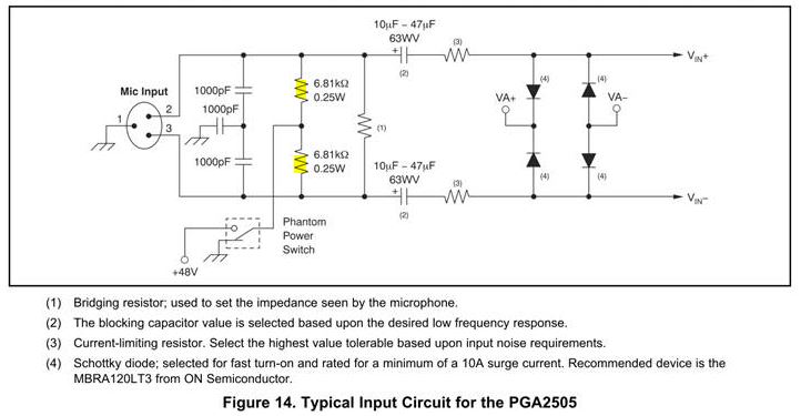
Thank you and Best regards,
Wayne Chen
06/25/2019

