This thread has been locked.

If you have a related question, please click the "Ask a related question" button in the top right corner. The newly created question will be automatically linked to this question.

OPA1692: OPA1692 Gain issue with high feedback resistor

Part Number: OPA1692

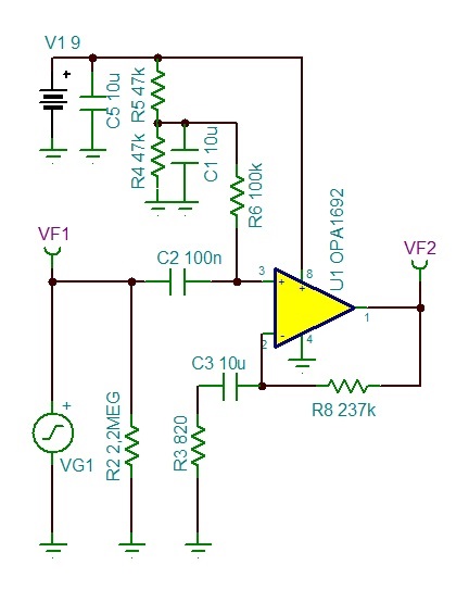
Hi, I've got 4 pieces of OPA1692. After simulating the circuit on TINA, I implemented the physical circuit. The problem is the gain: Theoretically and on TINA the result was the same G=49.24dB, but in the practical circuit the result was too far, G=45.9dB (more than 3 dB less). I checked all the components and connections (measuring all the resistor values) with no success. The only thing I imagine could result this discrepance is the feedback loop resistor too close to the input impedance (R = 237KOHM). The input impedance is 350KOHM. Is that statement correct? The ciruit is below:

And how to solve the gain issue?

My best regards,

Rubens Moreno

  • Hi Rubens,

    Can you please attach your TINA schematic? We will review. 

    -Tamara

  • Hi Tamara,

    Thanks for your attention.

    Below you've got the related TINA file.

    Gain OPA1692.TSCBest regards,

    Rubens

  • Hi Rubens,

    Thanks for sharing the TINA file. How are you physically measuring the gain? What frequency are you measuring the gain = 45.9dB case at? Can you also send me a picture of your physical circuit and measurement set-up?

    -Tamara Alani

  • Hi Tamara,

    Below you've got the information about the circuit:

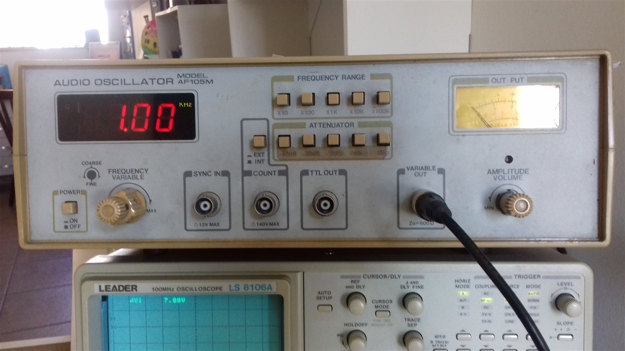
    The frequency is 1KHz.

    The power is a DC supply of 9.0V

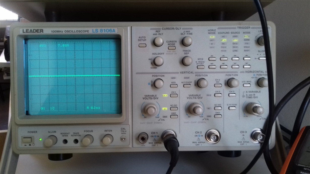
    The input signal is 13.7mVp-p @ 1KHz, measured with Leader Oscilloscope

    The output signal is 2.64Vp-p @ 1KHz, measured with Leader Oscilloscope

    The gain is G=20log(2.64/0.0137) = 45.7dB

    PS: with TINA , the measurements provide a correct gain of 49.24dB

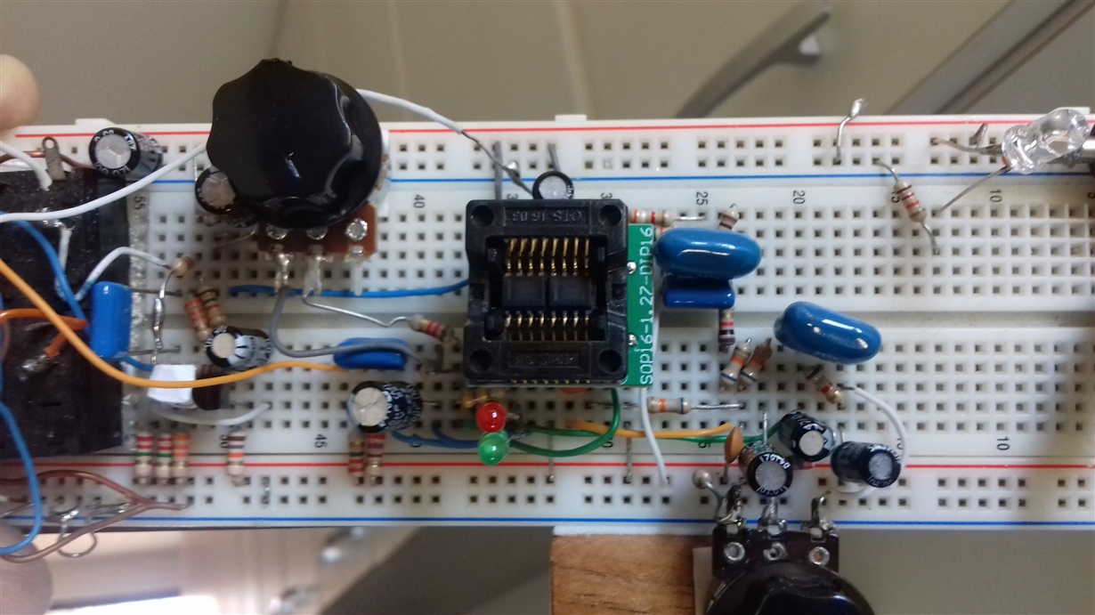
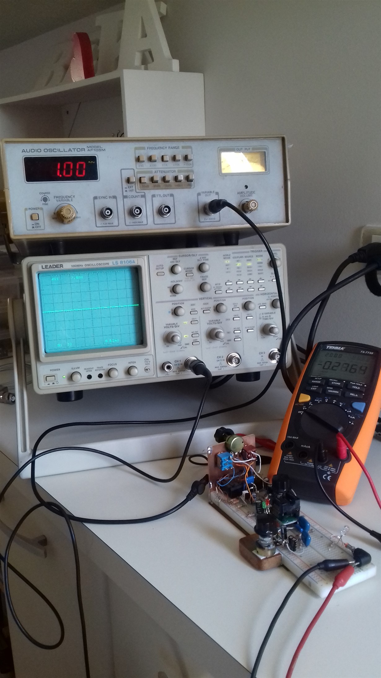
    Below there are the pictures of the setup I am using:

  • Thanks Rubens. I have a few more comments / questions for you.

    • I've noticed your physical circuit has extra peripheral components which were not in the initial schematic. Do you have a full schematic you can share with me? These peripheral components could have an effect on the gain. You may also want to consider just building the circuit you initially shared with me and see if you run into the same issue.
    • Can you measure the AC and DC input/output with a DMM? Can you also capture an AC scope shot of the input / output signal?
    • Is this circuit biased to 7.88V? The image was unclear, but we typically bias to mid-supply for full-range. 
      • Can you take a DC measurement with a DMM of the input / output with NO signal applied?

    Thanks for taking these steps with me, we'll figure this out.

    -Tamara Alani

  • Hi Tamara,

    I tried another Protoboard, with a brand new circuit and components. The result was correct. The gain was very close to the theorethical value (49.18dB). Probabily because of the measurements done with oscilloscope. I don't have a DMM.

    I am very sorry to cause an extra work for you guys. I would like to apologize myself.

    I consider the problem solved. Thank you very much for the attention on this matter.

    My best regards,

    Rubens