Because of the Thanksgiving holiday in the U.S., TI E2E™ design support forum responses may be delayed from November 25 through December 2. Thank you for your patience.

This thread has been locked.

If you have a related question, please click the "Ask a related question" button in the top right corner. The newly created question will be automatically linked to this question.

TAS2770EVM: Connecting EVM via I2S

Part Number: TAS2770EVM
Other Parts Discussed in Thread: TAS2770, PCM5102A, TAS2770YFFEVM

Hello,

I'm trying to connect my EVM 2770 board via I2S to the I2S output of my device. I did connect properly the FSYNC, SDIN, SDOUT, and CLK signals to the board. Now how do U switch the board from "USB audio" mode to I2S audio mode? Any specific jumpers to be set? I did put FSYNC jumper on J1, but still I get no audio. Anything to toggle from PPC3?

Cheers,

Alex

  • Hi, Alex,

    Our team will take a look at this and will provide an answer as soon as possible.

    Best regards,
    Luis Fernando Rodríguez S.

  • Hi Alex,

    Can you share a capture of your jumper settings?

    If you're using the same clock frequencies and data format as the USB source, no changes are needed on PPC3.
    I'll add a couple comments below:

    • What do you mean "FSYNC jumper on J1"?
    • You must remove the jumper on J2 to select external TDM source
    • External TDM source (FSYNC, SDIN, SDOUT, SBCLK) must be connected to J7

    Best regards,
    -Ivan Salazar
    Applications Engineer - Low Power Audio & Actuators

  • Hi Ivan,

    Sorry, I meant J11, not J1

    The external TDM source is connected to J7 correctly (I hope)

    J2 is even now (in USB mode) not connected

    Cheers,

    Alex

  • Alex,

    • No jumper is needed on J11, this is only used for soundwire mode.
    • You need to short J2 with a jumper (perhaps move the jumper on J11 to J2) in order to select external source.
    • Do you have GND reference shared between your source board and TAS2770EVM?

    Best regards,
    -Ivan Salazar
    Applications Engineer - Low Power Audio & Actuators

  • HI Ivan,

    Thanks for the recommendations, moving the jumper to J2 selects the external source (at least USB audio does not work anymore). I gave added a GND wire also between my device and the EVM. I still have no audio, but I have no MCLK on the control point, must be something with my device. Will look into it, and come back to you if it is s till not working.

    Cheers,

    Alex

  • Hi ivan,

    I have fixed my device, now I have MCLK and SDIN signals, but still no ah=udio comes out from the EVM board. Am I missing something else?

    Alex

  • Alex,

    Can you verify if your device has the same MCLK, BCLK and FSYNC frequencies as the TAS2770EVM?
    If they're not the same, TAS2770 may still be able to support it, but you need to adjust the clock settings in the Device Control panel.

    Best regards,
    -Ivan Salazar
    Applications Engineer - Low Power Audio & Actuators

  • Hi Ivan,

    I have this entry in my device tree (Allwinner H3 SoC)

    pcm5102a: pcm5102a {
            #sound-dai-cells = <0>;
            compatible = "ti,pcm5102a";
            status = "okay";
        };

        sound_i2s {
            compatible = "simple-audio-card";
            simple-audio-card,format = "i2s";
            simple-audio-card,name = "ti,pcm5102a";
            simple-audio-card,mclk-fs = <256>;
            status="okay";

            simple-audio-card,cpu {
                sound-dai = <&i2s0>;
            };

            simple-audio-card,codec {
                sound-dai = <&pcm5102a>;
            };
        };

    The tests I do as:

    speaker-test -D plughw:CARD=tipcm5102a -r 44100 -c 2 -F S16_LE -f 2000 -t sine

    In this case i get a noisy audio.

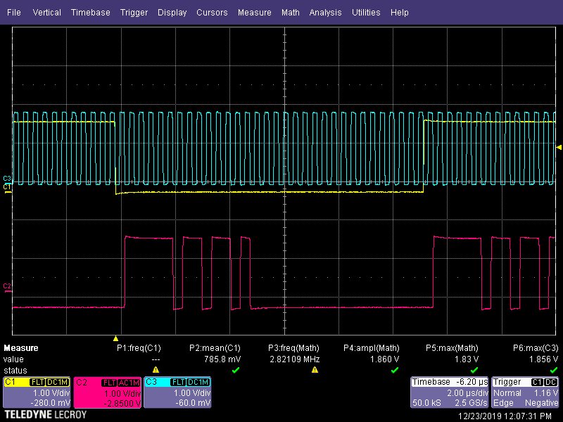
    What I can see from the scope is:

    - Bitclock is around 2.8MHz that makes sense

    - the FSYNC is 23-4 us, ie arounf 44kHz, which corresponds to SBCLK/FS ratio 64 ?

    - The data are present on one channel only-even if I have set 2 channels

    - The data are sometimes received during the "non-active" (high) state of the FSCLK


    The EVM is set to autodetect the SR and  SBCLK/FS ratio. If I set them off, I gave to set 44.1 SR and SBCLK/FS = 64 to have audioClick here to play this video

    The TDM is set to trigger on Falling edge of SBCLK, left justified. High to Low onFSYNK, 16 bits word length, 32 bit slot, selecting mono left channel only.

    Do you see something wrong?

  • Hi Alex,

    Unfortunately I cannot see your video, can you send it through a private message or email: ivan.salazar@ti.com

    If you click on the IRQ button from Device Control panel, do you see any flag that suggest an issue? Like TDM clock error?

    Best regards,
    -Ivan Salazar
    Applications Engineer - Low Power Audio & Actuators

  • Hi Ivan,

    May be the video is not necessary. I did some more tests, with 2 devices that do provide i2S (one of which is the one I try to make it work with TAS2770), and then compared the scope pictures with the I2S output of the USB chip on the EVM board. The only difference I was able to see is that in the case of the other 2 devices the FSYNC is with 50% duty cycle, while the one from the USB chip is just a single pulse.

    I was trying to set any combination of rising/falling edge triggers of SBCLK and FSYNC, but none of them did work.

    The I2S signal I have is 44100 kHz, stereo. 16bits, LE. The SBCLK has period of around 700ns, which is exactly what is expected-about 1.411 MHZ. The FSYNC is 44100 Hz, which corresponds to SBCLK/FSYNC ratio 32. Not sure if this is correct, because this would mean a single slot/channel, unless the slot size is 16 bits (which I have also tried to provide as a setting),  The slot select Config is set to provide Stereo Downmix. I have tried any combination of format (including BE)-no result .... I hear only audio clicks. The IRQ button shows TDM error, what shall this mean?

    BTW, It would be nice to have at least some kind of user manual explaining how to use the specific PPC3 plug-in, the generic PPC3 guide is only how to install, and the EVM user guide is not helpful either. Would be good to add at least s vocabulary for the used abbreviations and couple of lines about any of the option of the plugin. For example:

    1)  What is "Sample Ramp Rate", and how does it affect the audio output?

    2) Receiver offset-what is this? Measured in what: time delay, bits, slots?

    3) IRQ: How to use them? It is not quite intuitive to go to the IRQZ section, configure something there, and then clicking on the IRQ button to read them. How shall I decode/understand these IRQ states? For example, I see TDM clock error (latched), but if I set them to show the live state, then I see no error on live. What to do, and where to look for issues when a specific interrupt/error is triggered.

    4) Would be useful to have couple of examples showing I2S outputs with different sample format, and the corresponding  settings in the EVM device control

    I'm sure this would help reducing engineers development time, and also the number of support requests you are getting.

    Cheers,

    Alex

  • Hi Ivan,

    I'm sending the two photos-one of my setup, described in my previous message, and the one from the USB chip of the EVM board.

    The output from the USB chip is with FSCLK 48kHz, SBCLK 12,288 MHz, SBCLK/FSCLK ratio 256. One main difference: FSCLK is with a short pulse, while the others have 50% duty cycle. Also the signal is noisy, but it works. One more detail-as soon as I connect the GND of the scope probe, the audio becomes with clicks (The scope picture is with the probe GND attached, without it is even more noisy). But this could be an issue with the scope's ground.

  • Alex,

    The EVM default configuration is for TDM format data, as you have mentioned:

    • 8 channels
    • 32 bit slot length
    • 24 bit data length
    • FSYNC = 48kHz
    • SBCLK = 8*32*FSYNC = 12.288MHz

    I got confused by your last post: Are you having noise even if using the USB audio source on the EVM?

    Anyways, the device is able to work for your suggested configuration, I tried to replicate your input signals on my setup, please find attached some slides with the explanation and let me know if I'm having any differences on my setup.

    Best regards,
    -Ivan Salazar
    Applications Engineer - Low Power Audio & Actuators

    2770_i2s.pdf

  • Hi Ivan,

    Thank you for your reply.  I think I have already tried this configuration., but will try it again tomorrow. Whatever config i have tried, i get eithe n audio, or just noisy clicks. Hopefully will work with your settings.

    Cheers,

    Alex

  • Hi Ivan,

    Thanks to your recommendations, now we have one of the devices (the one that is providing 16bit samples, with 16 bit slot size, running at 48kHz SR. The picture on the scope is similar to yours, but recalculated for 48kHz.

    However, the other HW audio module that provides 16 pis samples on 32 bit slot (48 kHz) is a bit noisy on the EVM board. I have tried all possible settings in EVM, but could not make it work. Here are my settings:

    I2S audio:

    SR=48 kHz, FSCLK=48 kHz. SBCLK=3,072MHz, SBCLK/FSCLK ratio = 64

    EVM settings

    PLAYBACK: Sample Rate=44.1/48 kHz, Sample Ramp Rate=48kHz, SBCLK/FS Ratio =64,

    TDM: Edge Polarity = Rising Edge of SBKLK, Left justified, Frame Start Polarity = High to Low on FSYNC, Word length=16 bit, Slot length=32 bit, receiver Offset=1

    On the picture one channel is not shown because I'm using speakertest:

    speaker-test -D plughw:CARD=tipcm5102a -r 48000 -c2 -f 2000 -t sine

    which alternates the channels

    Do you have an idea what we are doing wrong on the EVM configuration?

    Cheers,

    Alex

  • Alex,

    Have you tried to set Receiver Offset to 0?
    From your scope capture, it seems there is no offset from FSYNC transition to data.

    Best regards,
    -Ivan Salazar
    Applications Engineer - Low Power Audio & Actuators

  • Hi Ivan,

    Yes, I have tried it today, also in cobination with all SBLK FSCLK triggers-it is still noisy. Are you sure this combination works on the EVM board? Did you test it with your PSIA interface?

    Cheers,

    Alex

  • Alex,

    Yes, this works on my setup, but its basically because I set a device configuration for the specific PSIA settings.
    It would be best to have the same data source to determine the specific data format you need.

    Can you share an audio recording of the noise you're hearing?
    Is it the same at different volume levels?

    Best regards,
    -Ivan Salazar
    Applications Engineer - Low Power Audio & Actuators

  • Hi Ivan,Here is the audio, I hid to change the volume while playing

    I have tried all combinations of falling/rising edges, receiver delays, etc. Nothing works. It is always noisy

    The audio is 2 ch, 16bit sample, 32 bit slot, ratio 64/ I'm testing with this command:


    speaker-test -D hw:0,0 -f 2000 -F S16_LE -r 48000 -c 2 -t sine                                         


    It generates 2000 Hz sine wave. and tests left/right chan one after another

    One more question-I find nowhere in the manual the format of the i2c commands to be executed in the i2c window. Could you point me to some document providing the format?

    Cheers,

    Alex

    P.

  • Hi Alex,

    For details on the i2c commands, you can refer to this Appnote: http://www.ti.com/lit/an/sloa265/sloa265.pdf#page=9

    But basically, for write, you use w -> Device Address -> Register Address -> Data

    Attached are updated slides with the test using PSIA and your described format (check the last slides). Based on how the noise sounds, it does seem like an error in clock/format configuration.
    Do you have an email address so I can reach out to you? Perhaps a remote session can help with this.

    3058.2770_i2s.pdf

    Best regards,
    -Ivan Salazar
    Applications Engineer - Low Power Audio & Actuators

  • Hi Ivan,

    This application note explains all about using the EVM board, thank you. Now I understand it better.

    About you slides-I have exactly the same settings as you, bu still no luck :( I would try to find another I2S source that provides the same format as my device, just to make sure the problem is not coming from it.

    You can email me directly at aleksandar@barix.com. The idea for the remote session is good, we need to find the good timing, because here now is 22h. I can open a teamviewer session for you.

    Have a nice weekend, and thanks a lot for your help

    Alex

  • Alex,

    The "Sample Ramp Rate" allows you to select the base multiple of your frame clock. Depending on the setting of "Sample Rate":

    • 44.1/48 kHZ
    • 88.1/96 kHz
    • 176.4/192 kHz

    The selection in Sample Ramp Rate of 44.1 kHz will set the device for the lower frequency in each of the above settings.

    "Receiver Offset" is in bits.  Standard I2S has a 1 bit offset.  This can be adjusted to match whatever format the data is being sent.  If this doesn't match the source, audio can easily become distorted, but you will not observe any clock errors.  It will just interpret the input data with the MSB starting in the wrong location.

    IRQ is an interrupt flag setting.  There is a device pin that will output either High or Low depending on the device settings.  This may be used as an input to the host to indicate an error such as a clock fault.  Additionally, within PPC3, the user is able to read back either latched or live fault flags. Typically, the host would read this fault back after the IRQ pin toggles and take appropriate action to handle the fault.  For errors with Frame/Word Clock or with Bit Clock, we can check the latched flags after powering up the device.  Given any mismatch between device clock settings and the input source, I would expect to see the device enter shutdown immediately and to see the "TDM Clock Error" flag assert.  To check the flag, click the IRQ button and then click "Read".  If any fault condition is read back, the grey circle will illuminate orange for the corresponding flag.  This is a self clearing register, so a second read will show this being reset.

    For the case you suggest of a 44.1 kHz input at a 16 bit word, and a SBCLK clock ratio of 32 I would set the device as shown below:

    Having the offset set to '1' here will expect the MSB of the data to be the second bit following the falling edge of frame clock.  This is typical case for I2S, but your source may be transmitting with no offset.  

  • Hi Scott,

    Thanks for your nice explanation, I was wondering what this "Sample Ramp Rate" means. now is clear.

    About the settings you propose-yes, it is exactly these that do work with our other  audio module, that provides 16 bit samples on 16 bit slots, 44.1kHz. THE EVM board plays this i2s format just fine.

    On the contrary, the EVM cannot sync to our new audio module, that provides 16 bit samples, 32 bits slot, 48kHz. Whatever settings I do put in the EVM, I have always noise, and TDM Clock error on the IRQ values.

    What it makes it even more confusing is that the TDM_DET register is 0x23, which is what I would expect: ratio=64, and SR-48kHz. Then where this "TDM Clock Error" is coming from?

    I'm sending you a snapshot of my scope to see the data format-you can see that it is a perfect i2s format.

    Cheers,

    Alex

  • Alex,

    The IRQ "TDM Clock Error" flag is read from register 0x24 bit 2. I've tried to recreate your setup:

    I likewise read back 0x23 from register 0x77.  I am able to play a continuous sine tone that does not sound distorted with the settings below. I am transmitting with a 1 bit offset and have the device set to receive the same:

    If with these settings you still get clock errors, I would check the quality of the I2S signal on the EVM.  Was your scope capture taken on the EVM?  Typically it is best practice to add a GND return for each signal when pairing clocks from one system to another.  Without a sufficient GND return the data will easily become corrupted.  

    Also, please be sure that your input logic levels match the expected levels on the EVM.  Jumper J1 for VCC select - I2S will set the expected input voltage.  If you have it set to 3.3 V and are driving with 1.8 V, it may not latch the incoming data correctly. 

    It may be that since the device recognizes the clock frequencies that you are just getting random glitches that trigger the clock error. 

  • Hi Scott

    My setup is exactly as yours, even the picture on the scope is the same.

    As for the ground-I have connected the ground of my audio module to one of the pins on the input connector of the EVM.  On the same pins I have attached the grounds of the scope probes. J1 is set to 3.3V logic. However, I see that the signal range on my and your scope pictures is about 2V-this shall be fine. The signals I measure directly on the EVM test points.

    Tomorrow I will try with couple of other modules just to exclude the possibility of a faulty module ..... even if the signals seem to be fine on the scope.

    Alex

  • Hi Scott,

    One update: today we have received another TAS2770YFFEVM board, and tried with it. The result is the same-still noisy output, which might mean that the audio comes already distorted from our audio module. Will dig in that direction in the first days after Christmas. I also did make a screenshot of the scope, this time measuring directly on the i2s output of our module instead on the control points of the evaluation board. It is the same, no difference.

    For me the format is:
    16bits sample, 32 bit slot, x64 ratio, trigger on high-to-low of frame clock, 1 bit delay. latch the first data bit on falling edge of bitclk.
    However does not work neither with these settings, nor with any other combination

    Thank you very much for your support, and have nice Christmas holidays,

    Cheers,

    Alex

  • Hi Alex,

    Please let us know how your tests go.
    We'll follow up on your questions over the next week.

    Best regards,
    -Ivan Salazar
    Applications Engineer - Low Power Audio & Actuators

  • Hi Ivan!

    HappyNew Year and all the best for you and your family!

    Our office is closed till 07.01. Last thing that I hav tried the last day before the holidays was to test also with the new YFFEVM board that we have ordered. The result was the same-distorted audio. Once I'm back, I will investigate more on the side of our audio module ,  and will keep you informed.

    Thank you for following up on this issue, we really appreciate it!

    Cheers,

    Alex

  • Hi Ivan,

    Finally I have some update for you. We made many tests here, including using two boards using TI PCM5102a as I2S source and sink. The EVM board was able to play form the I2S source properly, The other board (I2S sink) was able to play from our audio module. We did further checks and found that the bitclock of our audio module is not very stable, so this might be most probably the cause. We will go investigating to find the reason for this instability, but in the meantime-do you have any idea if it is possible at all to configure the EVM board in a way that it is more tolerant about the clock?

    Cheers,

    Alex

  • Hi Alex,

    I'll check if something in the device can be configured to let it resume operation after clock error detection, without complete device initialization.

    Best regards,
    -Ivan Salazar
    Applications Engineer - Low Power Audio & Actuators

  • Hi Ivan,

    Finally we made it working!

    What we had to do is to:

    1) revert a commit, introduced in kernel 4.16, to make a "better accuracy" of the parent clock by using a sigma-delta modulation. This was in fact the change that was causing the fitter of the bitclock, that was preventing the TAS-2770 to work properly.

    2) Hardcoded the clock dividers in sun4i-i2s.c driver to match the config for 44.1kHz, 8 channels, 16 bit data, 16 bit slots

    3) configured our devicetree to use the pcm5102a codec in the mode mentioned above

    Like this our module works with TAS-2770 and TAS-6421 amplifiers. The second one also was an issue, because our module does not provide masterclock, but just bit clock, frame clock and the data. However, when we use the bitclock as master clock for TAS-6421 with the 8 channels format, it switches to TDM, and works pretty well.

    Thank you very much to you and all involved people from the TI support helping us on this issue!

    Cheers,

    Alex