This thread has been locked.

If you have a related question, please click the "Ask a related question" button in the top right corner. The newly created question will be automatically linked to this question.

TAS5613 Inductor choice

Other Parts Discussed in Thread: TAS5613, TPA3100D2, TAS5613A

Hi All,

We're designing a power output stage with the TAS5613. We've built a prototype board basing on the schematics of the TAS5613 evaluation board but i cannot find the toroidal inductor (toko C3B-A0336). We tried replacing with http://docs-europe.electrocomponents.com/webdocs/002b/0900766b8002b270.pdf this choke, but it did'nt worked.

We're trying to use the chip in BTL configuration (M1 M2 M3 = 0 1 0) but at the outputs A and B (without any LC filter) i can read the same PWM signal and not two opposite-phase signals as expected. Even with the correct LC filter at the output we won't be able to get any signal, cause the two filtered PWM waves will mix in-phase producing no output.

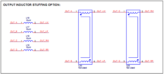
Is there any configuration we're missing or should we use mutual coupled inductors to change the phase of one wave? We thought of this last option just because of the symbol used in the evalutation board schematics.

Can you please suggest any troubleshooting procedure to solve filter-related issues?

Thanks in advance for your help,

Best regards

-----------------------

Normal 0 14 false false false IT X-NONE X-NONE MicrosoftInternetExplorer4

Eng. Andrea Campanozzi

ELETECH S.r.l.

Email: a.campanozzi@eletech.it

Tel: +39 080 373 9023

Fax: +39 080 375 9295

Web: http://www.eletech.it

  • Andrea, your MODE setting 010 selects BD modulation at the outputs.  With BD modulation , when the input signal is zero the outputs switch almost in parallel, with small phase differences that produce narrow alternating differences between the 2 outputs.  These enable the feedback system to maintain the DC output point.  As input signal increases from zero, the duty cycles of the positive and negative outputs shift in opposite directions.  This produces difference pulses between them that drive the load.  A complete description of BD modulation can be found in our TPA3100D2 data sheet SLOS469F.

    Regarding the toroid inductor, we can provide the drawing, which I have attached.  You are welcome to have this inductor built for you.  There are other sources as well.  Some of our European customers have used Wurth Electronics.

    The important specifications for the inductor are the following.

    - Nominal inductance 10uH;  minimum working inductance (from tolerance, temperature and saturation): 7uH (see page 4 of TAS5613 data sheet SLAS676 or TAS5613A data sheet SLAS711).

    - DC current rating at least 9A;  DCR less than 30milliohms.

    - Core losses no greater than copper losses.

    Regards,

    Steve.

    TIC-INDC-020(1.00).pdf
  • Thank you for your quick answer,

    we did it by making the inductor by ourselves and it worked properly.


    regards


    Andrea