This thread has been locked.

If you have a related question, please click the "Ask a related question" button in the top right corner. The newly created question will be automatically linked to this question.

OPA1637: LPF design based on OPA1637

Part Number: OPA1637
Other Parts Discussed in Thread: LME49724

Hi all,

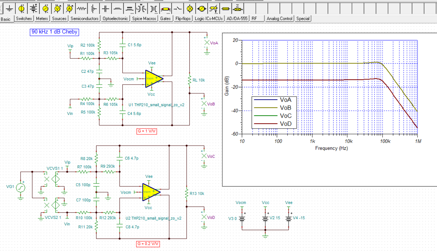
Now I'm trying designing a LPF based on a full differential op amp opa1637. Moreover, the LPF needs a 0.2V/V attenuation and 100kohm input impedance. But t  seems that the Filter design tool does not support full differential op amp.Is any suggestions?

  • Hi JimmyLee,

    TI's Filter Designer currently doesn't support fully differential (FDA) filters, or gains of less than 1 V/V so Filter Designer isn't gong to do what you need. There are other filter programs that can synthesize FDA active filters and one of those could be used.

    The multiple-feedback (MFB) low-pass filter topology can be set up for a gain of less than 1 V/V, and can be altered to accommodate a differential input. I covered how to convert the single-ended input MFB to a differential input MFB in TI's 3rd quarter, 2009 Analog Applications Journal, Pgs. 33 - 38 Here's a link to the article:

    http://www.ti.com/lit/an/slyt337/slyt337.pdf

    If you know the low-pass cutoff frequency, the filter response such as Butterworth maximally flat response, and the filter order required (often 2nd order), I should be able to help you design a active low-pass filter that uses the OPA1637 audio FDA op amp.

    Regards, Thomas

    Precision Amplifiers Applications Engineering

  • Thank  you  Thomas, the filter pass band(20~20Khz) ripple is less than ±0.1dB,Butterworth maximally flat response should be OK. I'm afraid I can't  directly give you the cutoff frequency , but it should be the smaller the better while meeting the following  response demands:

    20~20 khz,less than ±0.1dB;

    20~45 khz,less than ±0.5dB;

    20~90 khz, less than ±1dB.

  • Hi JimmyLee,

    The band-pass ripple will only be as good as the Butterworth filter produces and it produces the flattest pass-band response of the various filter response types. If I interpret your specifications correctly the low frequency cutoff would be 20 Hz with 0.1 dB ripple. Below that frequency the attenuation would increase. Then, on the high end the cutoff would be 90 kHz with 1 dB ripple, and attenuation would increase beyond that. There will be problems achieving this response using the common MFB topology which is necessary for a practical differential filter design.

    The lower cutoff frequency needs to be specified as number such as -1 dB, or -3 dB. 0.1 dB is impractical. And on the higher frequency end the MFB response begins deviates from ideal with a 1 dB ripple at 90 kHz. The OPA1637 gain bandwidth of 9.2 MHz is a bit lower than what is needed. What is really needed are -3 dB filter specified cutoff frequencies if possible.

    Regards, Thomas

    Precision Amplifiers Applications Engineering

  • I'm sorry I may have misled you. Actually, I need two LPFs which have the same  pass-band ripple ±0.1dB and different gain. The first one needs  1v/v(0dB) gain,frequency response is given as above, and the second one has  0.2V/V(-13.98dB)gain,so the frequency response should like below:

    20~20 khz,less than -13.98±0.1dB;

    20~45 khz,less than -13.98±0.5dB;

    20~90 khz, less than -13.98±1dB.

    as per my  FilterPro simulation with single input  single output , the cutoff frequency(-3dB) is about 140Khz,I'm not sure this data  also applicable for the filter has - 13.98dB gain.

  • Hi JimmyLee,

    When I take into consideration the ripple at each of the high end frequencies all that can realistically be realized is either a filter that has a maximum ripple of 0.1 dB at 20 kHz, or 1 dB at 90 kHz, but not both. Therefore, 0.1 dB can be specified at 20 kHz and then the attenuation would be much greater at 45 kHz and 90 kHz. Or, the filter would be designed for 0.1 dB over an entire passband of 90 kHz and then the attenuation would increase beyond that top end.

    When I review all the requirements 100 k input resistance, fully differential input/output, maximum 0.1 dB ripple at 20 kHz, 0.5 dB at 45 kHz and 1 dB at 90 kHz, I am not finding an active filter topology that can support all of these requirements simultaneously. The OPA1637 does not have high enough gain bandwidth to support a 0.1 db ripple response at the high end of the frequency range using the required MFB topology needed for a fully differential low-pass filter.

    If the filter requirements can be relaxed, then there may be a reasonable solution. But as is, the OPA1637 and common MFB topology don't appear to be able to meet all the response requirements.

    Regards, Thomas

    Precision Amplifiers Applications Engineering

  • Hi Thomas,

    Could you post the  response curves of maximum ripple of  0.1 dB at 20 khz and 1 dB at 90khz?maybe  we can relax requirements.  Regarding gain bandwidth,do you have a better choice, the filter input  voltage  supported should be up to 10Vrms

  • Hi JimmyLee,

    I have studied your filter requirements and synthesized four separate low-pass filters that utilize the OPA1673 FDA. There are two 20 kHz 0.1 dB Chebyshev designs having gains of 0.2 V/V and 1 V/V. And two 90 kHz 1.0 dB Chebyshev designs also having gains of 0.2 V/V and 1 V/V. The results from simulation are shown below. Note that since the OPA1637 is in preview mode we don't have a released simulation model for it available. I used a similar FDA model, the THP201 for the simulations. Its model is not finalized, but usable for demonstrating the active filter responses.

    Keep in mind that passive component tolerance variances, op amp variances and circuit parasitics may modify the responses somewhat.

    Regards, Thomas

    Precision Amplifiers Applications Engineering


  • Hi JimmyLee,

    Note in the second set of schematics for the previous response that VCVS1 and VCVS2 are connected to Vip and Vin, respectively. I captured the image at some point when I was doing something else and the wire connections were not present at that moment. The results seen in the graph are valid because the connections were indeed in place during the simulation.

    Regards, Thomas

    Precision Amplifiers Applications Engineering

  • Hi Thomas,

    Thank you for your  help. In view of OPA1637 being in preview, I've replaced it using LME49724,and I've simulated in Tina successfully as you posted above. but I have another question how to  achieve the 100k input  impedance 

  • Hi JimmyLee,

    The issue at hand is that there are only so many degrees of freedom one has when synthesizing filters before something has to be compromised. The problem with setting the input resistor R1 to100 kilohm is that capacitors C1 and C2 become smaller and smaller in value, especially C1 in the 90 kHz filter. C1 becomes less than 10 pF and then the input capacitance of the op amp and circuit stray capacitances begin to alter the filter responses.

    I re-synthesized the filters so that the input resistor in each case is 100 kilohms, then worked for a combination of other R and C values that provided the 0.1 and 1 dB Chebyshev responses at 90 kHz and 20 kHz, respectively. The results in actuality may be a little different because of the capacitance issues I mentioned. The filters that resulted are shown below.

    Do note that even though the input resistor has been set to 100 kilohms that across frequency the active filter input impedance changes. That is the nature of RC input active filters which includes the Multiple Feedback (MFB) topology.

    Note that if you do decide to use the LME49724 instead of the OPA1637 in the actual design, the LME49724 is supported by a different TI business unit and they would provide any support moving forward.

    Regards, Thomas

    Precision Amplifiers Applications Engineering

    20 kHz

    90 kHz