


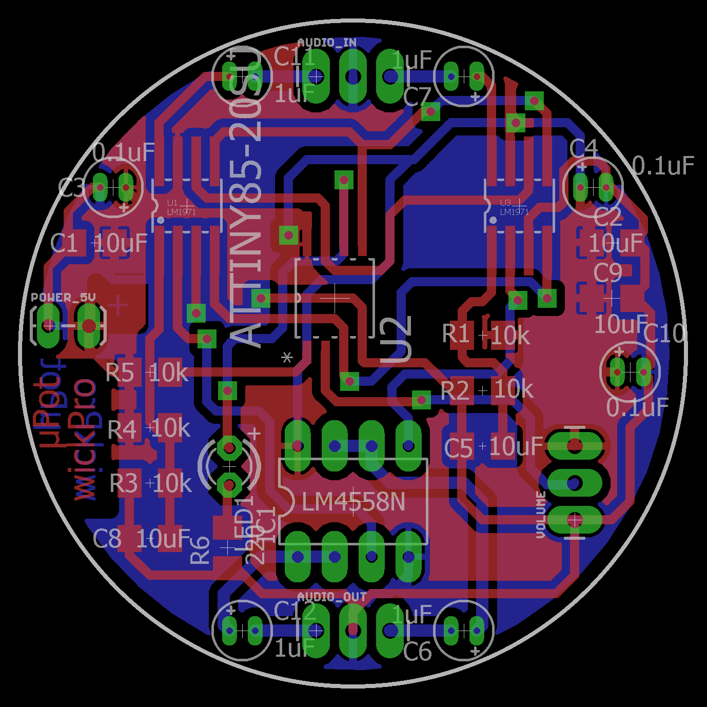
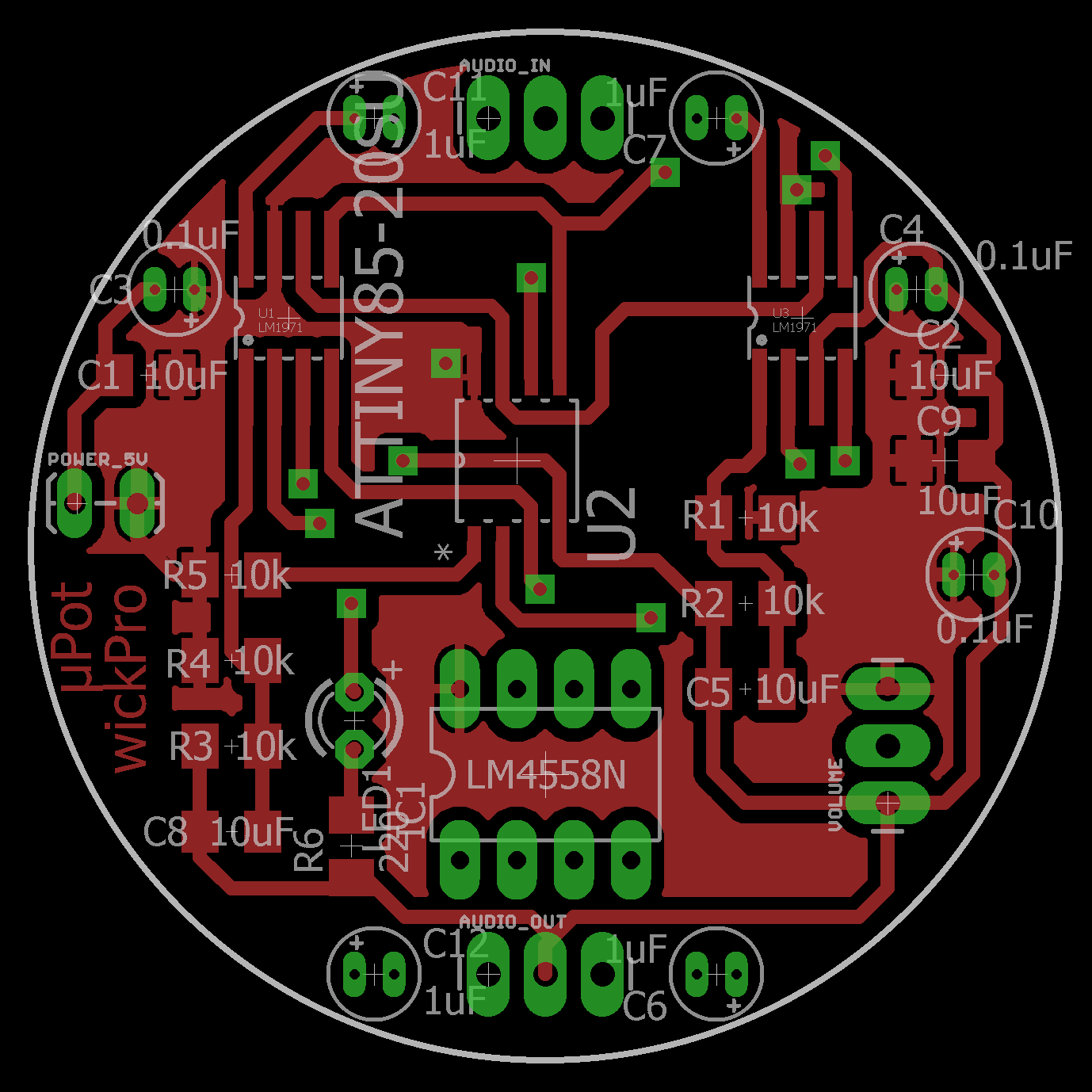
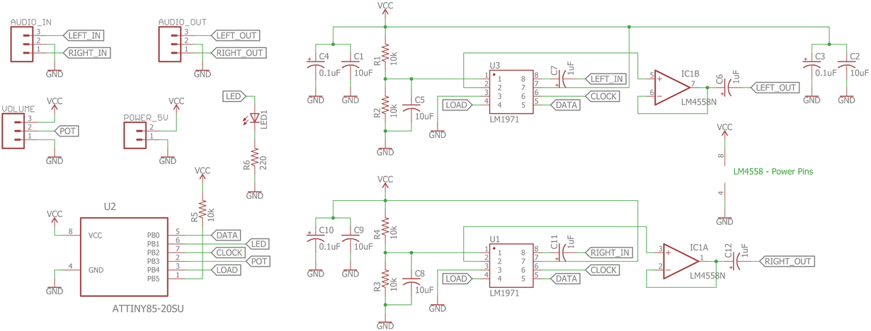
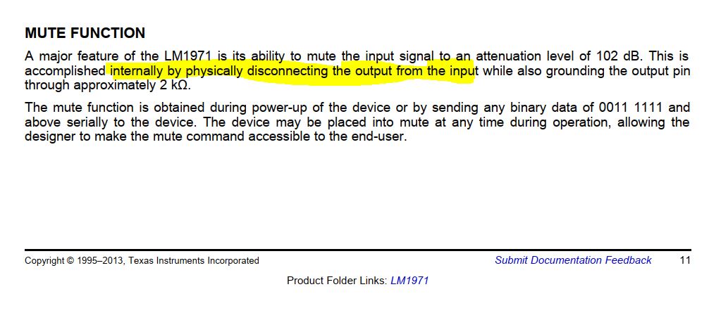
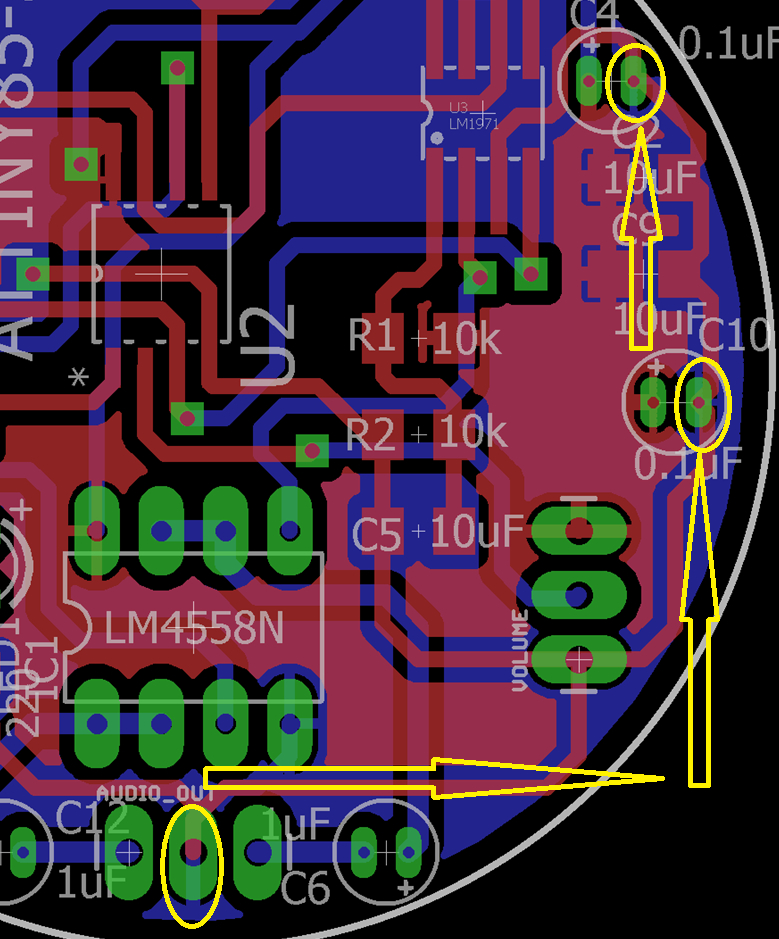
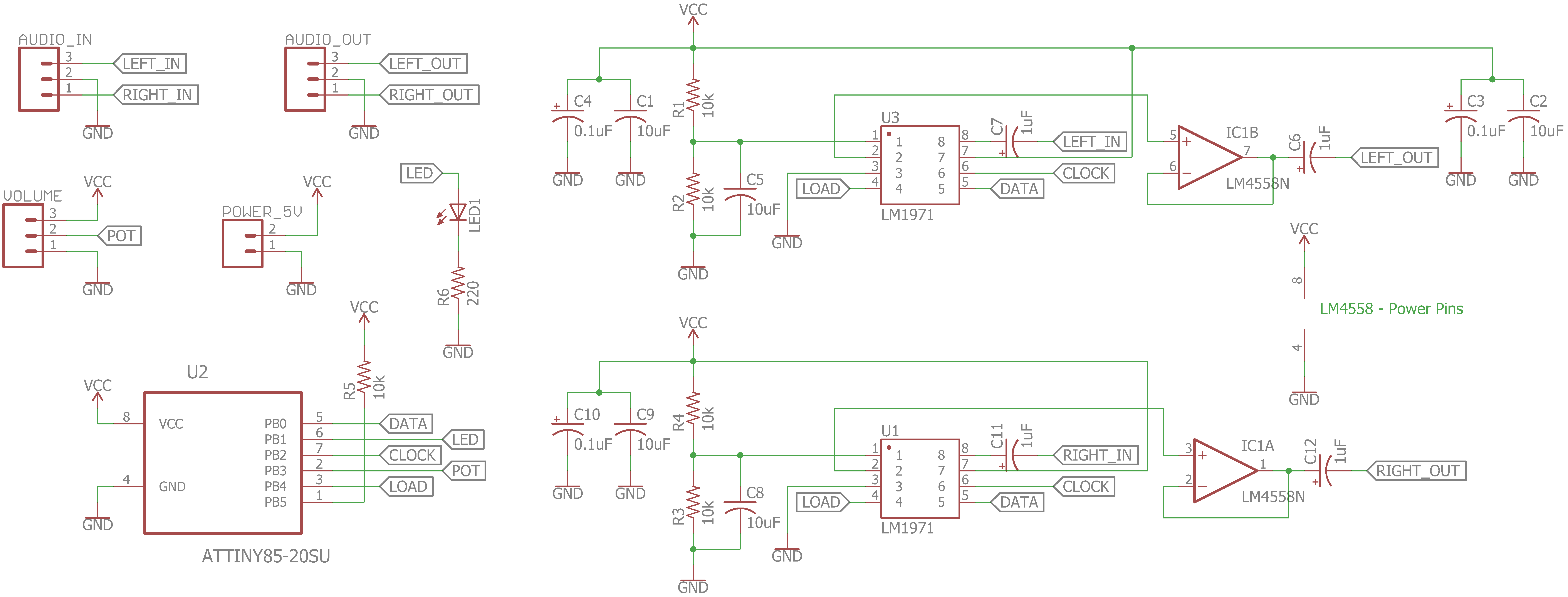
Recently I created a two channel audio attenuator using two LM1971 s. Everything works fine except mute function. when muted, I can hear the audio slightly from the output.
Design files attached.
Any guidance appreciated.
Thanks.
Original question:

Recently I created a two channel audio attenuator using two LM1971 s. Everything works fine except mute function. when muted, I can hear the audio slightly from the output.
Design files attached.
Any guidance appreciated.
Thanks.

