This thread has been locked.

If you have a related question, please click the "Ask a related question" button in the top right corner. The newly created question will be automatically linked to this question.

TPA6166A2: INL/INR allowed input range

Part Number: TPA6166A2

Dear Ti team,

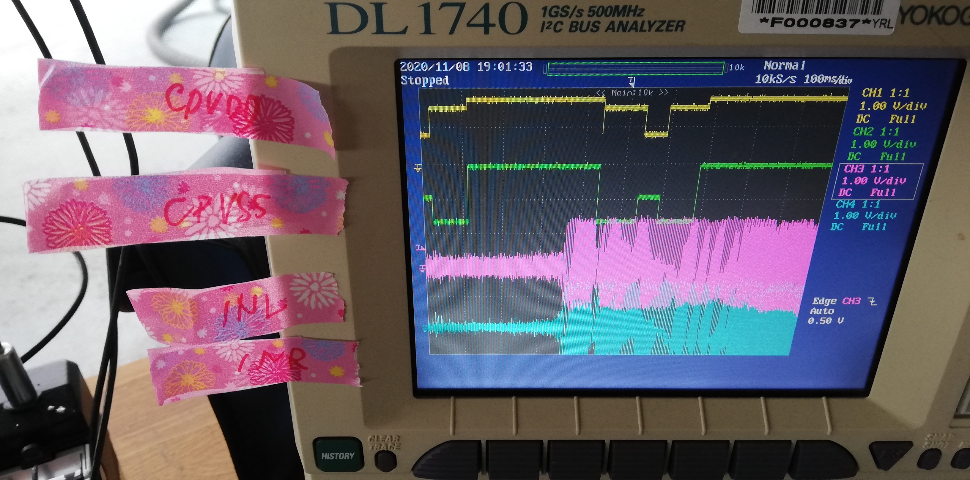
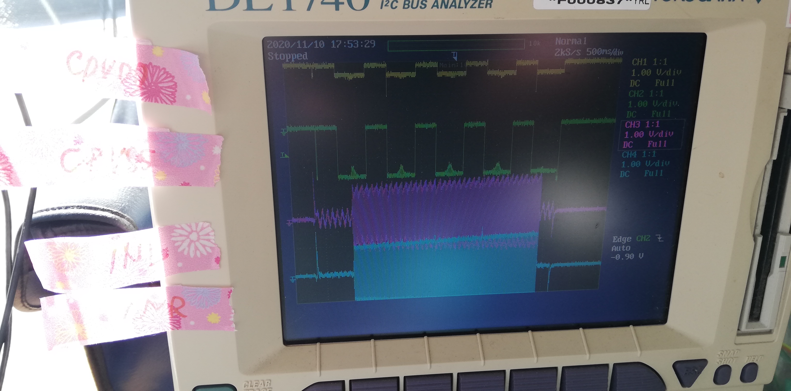
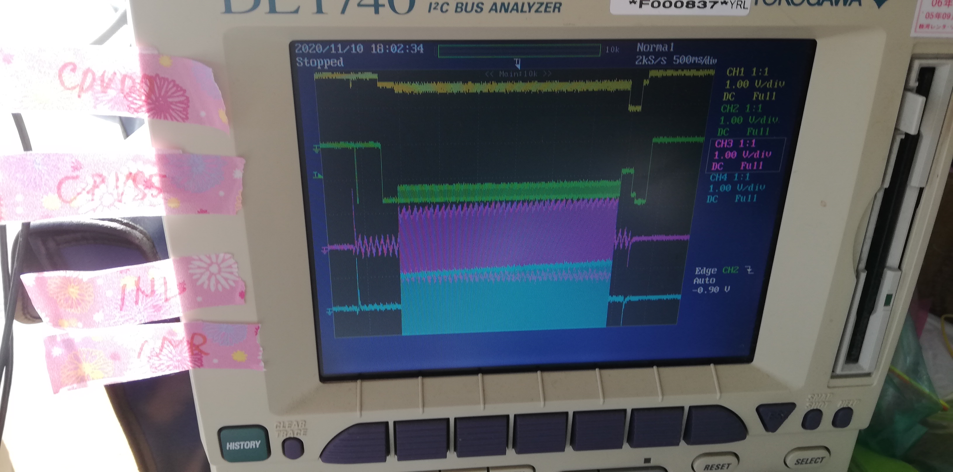
Would you let me know INL/INR allowed input range?

In my understanding,  that is from CPVSS to CPVDD.

Since Charge pump circuit is implemented,  that is CPVSS(-1.8V) to CPVDD(1.8V) when VDD=1.8V??

BR,

Matsuda 

  • Is this waveform for CPVDD/CPVSS/INL/ILR correct figure??

    we observed playback sound is breaking up when this waveform itaken.

    INL/INR is input as -1.5V to 1.5V.

    But CPVDD-CPVSS(=should be vdd for amplifier) cannot catch up with INL/INR change. (= sometimes CPVDD-CPVSS is lower that INL/INR)

    Is this OK?

    BR,

    Matsuda

  • Hi, Matsuda,

    The analog inputs are limited from GND to MICVDD level. In addition, you would need of inputs capacitors since the analog inputs have common-mode level. In that way, there won't be risk of having an incorrect configuration.

    Best regards,
    Luis Fernando Rodríguez S.

  • Hi Luis-san,

    • Yes. We already have implemented input capacitor for INL/INR.

    Waveform(INL/INR) is TPA6166A2 side's one which signal from out codec IC have passed thorough these input capacitor.

    So If you want us to apply bias , so as to keep  "GND to MICVDD level" requirement, it should be done by TPA6166 side.

    Please let me know how to do it.

    • I will show you my new finding.

                I am still headphone amp is working based on the power (CPVDD/CPVSS).

                So input amplitude for amp should be within CPVSS to CPVDD.

                Depending on HP impedance, control for CPVDD/CPVSS is sometimes wrong, which result in failing amplified sound output.

                Please let me know if we can survive with sw counter measure or any other solution.

                1.

                Here is waveform for CPVDD/CPVSS/INL/INR with famous iphone genuine headset. 

                In this case, sound played back by TPA6166 is breaking up.

                Sometimes we can observe amplitude of CPVDD-CPVSS is lower than one of INL/INR.

                This is failing case.    HP impedance is 30.5ohm in my measurement.              


    2. 

                Here is waveform for CPVDD/CPVSS/INL/INR with SONY MDR-EX150 headset. 

                In this case, sound played back by TPA6166 is Ok.

                We can observe amplitude of CPVDD-CPVSS is same level as one of INL/INR always.

                This is OK case.             HP impedance is 18.3ohm.

    BR,

    Matsuda


  • Hi, Matsuda,

    Could you share the circuit schematic in order to have a better approach to this case? I don't remember to have seen it in previous posts.

    Thank you.

    Best regards,
    Luis Fernando Rodríguez S.

  • Hi Luis-san,

    You can see TPA6166A2 in center bottom,

    BR,

    Matsuda

  • Hi, Matsuda,

    Thank you for providing the circuit diagram.

    Do you have details about the output capacitance that each headphone load has? The output capacitance is limited as mentioned in the recommended operating conditions of datasheet:

    https://www.ti.com/lit/ds/symlink/tpa6166a2.pdf#page=4

    This output capacitance may affect the behavior of the device.

    Best regards,
    Luis Fernando Rodríguez S.

  • Hi Luis-san,

    There is no way to reduce load capacitance.

    I believe there should be test mode to enable charge pump voltage to be fixed in maximun (CPVDD=1.8V, CPVSS=-1.8V).

    Would you let me know how to do this ??

    We are very concerned with not supporting  famous Iphone earphone in our product.

    Even with tradeoff between power comsumption and iphone earphone support, I would like to put solution for it.

    BR,

    Matsuda 

  • Hi, Matsuda,

    Thank you for your response.

    Have you tried to use the Bit 2 of register 0x1e in order to allow a higher threshold for the power supply switch? Do you have different results with this bit?

    Best regards,
    Luis Fernando Rodriguez S.

  • Hi Luis-san,

    Even if  Bit2 of regitser 1e is set 1 or 0, Still I observed same phenomena.

    Please let me know how to fix power supply to +-1.8V independend of input amplitude.

    If you hesitate to disclose test mode here, please let me know contact point. 

    BR,

    Matsuda

  • Hi, Matsuda,

    I think in this case it is not possible to make the power supply independent of the input amplitude. The TPA6166A2 is a Class-G amplifier that adjust the power supply level based on the input signal level.

    There's no way to modify this behavior even in test mode.

    Best regards,
    Luis Fernando Rodríguez S.