This thread has been locked.

If you have a related question, please click the "Ask a related question" button in the top right corner. The newly created question will be automatically linked to this question.

TIDU765 amplifier has worse distortion than inverting amplifier?

Other Parts Discussed in Thread: TINA-TI

's TIDU765 www.ti.com/.../tidu765.pdf application note says that one of the benefits of this circuit is that:

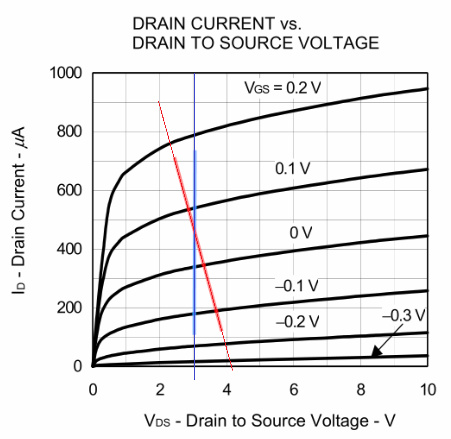
"the voltage at the drain of the microphone JFET varies very little, potentially reducing distortion caused by channel length modulation in the JFET"

I've simulated replacing our non-inverting amp with this transimpedance amplifier, and the voltage at the drain of the JFET does indeed become constant, but the distortion only increases, no matter what simulation parameters I use.  (Real op-amp models, ideal op-amp, changing drain resistor, etc.)

  • Inverting amp: 15 μV noise, 0.34% THD
  • TI amp: 11 μV noise, 0.55% THD

I am using an actual JFET spice model, though, not the model in the paper.  Maybe that's why?  I tried to modify a stock JFET to more closely emulate a real JFET used in electret capsules, but maybe my model's not good.

  • Also when I try to do a TINA Fourier Analysis of the example circuit, the voltage increases every time I run the simulation.  Billions of volts in one test run, then I run it again and it says trillions of volts, ...

    then Cancel and then Fourier Series again:

    Why is it increasing every time??  Each analysis shouldn't remember anything about the previous one.

  • Hi Jonathan,

    To be honest, I've never had much luck simulating THD in TINA. I agree that the amplitude should not increase with each run. It would be best to measure the performance of the circuit in the lab to get reliable results.

    Can you post your TINA file to see if I can get replicate the issues?

    Thank you,

    Tim Claycomb

  • Hi Jonathan,

    I was able to find some additional information that might be the cause of your issues. Please see below forum posts.

    Why TINA-TI shows THD=0.035% for Voltage Generator with Ri=0 ? - Simulation, hardware & system design...

    e2e.ti.com
    Other Parts Discussed in Thread: TINA-TI I performed Fourier series for my schematic and got about 0.036% THD. Base frequency 10khz, start time is 10msec, end time

    Thank you,

    Tim Claycomb

  • The amplitude increasing with each run is from the TI TINA file at

    Open "Electret Microphone Pre-Amp.TSC"

    Analysis -> Fourier Analysis -> Fourier Series

    4.27 mV

    Cancel

    Analysis -> Fourier Analysis -> Fourier Series

    422 mV

    Cancel

    Analysis -> Fourier Analysis -> Fourier Series

    91.8 V

    Cancel

    Analysis -> Fourier Analysis -> Fourier Series

    12.4 kV

    etc.

    This doesn't happen with my simulation, so I wonder if it's due to the electret model in the TI simulation?

  • Here's my simulation.  I don't really know if my JFET modification is correct, but it seems to behave reasonably realistically?

    TI electret preamp.TSC

  • Hi Jonathan,

    The JFET model may have an effect on simulation. When I remove the JFET and input voltage source and replace it with a current source. I get much better performance. However, it seems too good to be true.

    I think the best way to test the distortion performance is to build it up and test it. We have a few EVMs that you could populate and test this with a few modifications. I think the easiest option would be to use the DIY-AMP-EVM. This has multiple circuit configurations on it that should allow you to quickly build a prototype of this circuit and test it out.

    Thank you,

    Tim Claycomb

  • Well the point of this simulation is to understand the circuit shown by TI and the claim about "potentially reducing distortion", which makes some sense to me because VDS is kept constant (blue line), so there wouldn't be channel-length modulation:

    But I guess there is another form of distortion that is stronger here?  Or maybe the red line really is just more linear for this type of JFET?

    Do you see the ever-increasing voltage when running Fourier transforms on "Electret Microphone Pre-Amp.TSC"?  That seems like a bug in TINA-TI or in the TI electret model.

  • Jonathan,

    I extended your red and blue lines then calculated the gain (delta drain current / delta Vgs) over each 100mV of VGS change.

    In the math generated plot, the gain of the mic is not linear. Non-linearity is not good for THD.  The DC operating point matters.

  • In an electret capsule, Vgs is always 0, and a typical signal is 13 mVpk, so it looks like both curves are similarly nonlinear in that region?

  • Jonathan,

    When measuring THD try not to start at time zero. looking at 2ms to 4ms can be better than 0ms to 2ms. The initial t0 might not be perfect.

    The large majority of the THD is caused by the JFET gain which is  (Vgs + Vt)^2 where Vgs peak to peak is less than Vt. So output will be a small section of a squared curve. It is sort of linear, but not not really linear if looking closely.

    Take away the op amp connection and check THD of just the JFET output and the THD there will be just as high.

    I plotted the DC curve for VGS +/-13mV and subtracted out the DC center and DC average gain to get the non lin error for just FET (no op amp).

    VOUT error vs VIN