This thread has been locked.

If you have a related question, please click the "Ask a related question" button in the top right corner. The newly created question will be automatically linked to this question.

SRC4392EVM-PDK: Signal Routing

Part Number: SRC4392EVM-PDK

Hello,

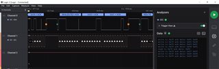
I would like to control a SRC4392EVM-PDK by a MSP432-P401R. I use I2C to write to registers. I checked it with a logic analyzer and it is working.

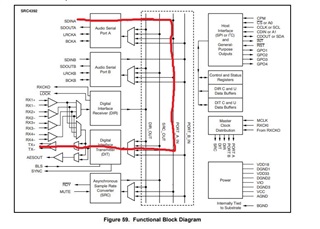
Now I want to route the following signal: I2S --> Port_A_IN --> DIT --> tx_OUT (like shown in the below picture):

I did write to the following registers:

Register    Data

0x01         0x40    RESET (I built in a delay after the reset command)

0x01         0x34    I would like to only use the used blocks (Port_A , TX) - Can PDALL bit be neglected?

0x03        0x01    Input Signal of I2S shall be in Slave Mode

(0x04        0x01     - not needed, since Port_A is in Slave Mode)

0x07         0x10     MCLK Input, Clock Divider 256, Port_A as Input

Do I need to read/write to each register that the default values are valid? I already saw in some of the forum replies here that the registers are initialized with 0x00.

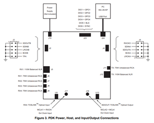
Port_A of the SRC4392EVM-PDK is now connected to the output of a Audio Precision 2722:

BITCLK to BLCLK

FRAMECLK to LRCKLA

DATA_Out to SDINA

MASTERCLK to MCLK2=MCLK

The input of Audio Precision 2722 is connected to TC Out of  the SRC4392EVM-PDK.

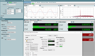
When I now generate a 24 bit 48kHz I2S signal with the Audio Precision and supply into the SRC4392EVM-PDK, I do not see the signal on TX output, flowing back to the Audio Precision.

I already tried some configuration examples from the forum, but nothing worked so far.

Do I have maybe any misinterpretation in my setup?

Hope you can give me some advise and support.

Thanks and best regards,

Michael

  • Hi Michael,

    The first thing I would recommend would be to write a register and make sure you are able to read back your written value over I2C to confirm that the SRC is in fact being programmed. 

    I would also check that the port you are using on the board is the correct one as the ports labeled A and B on the DAIB motherboard do not correspond to Ports A and B from the SRC daughterboard (an unfortunate oversight). If you are using Port A in the SRC then your connections should be made at J4 on the DAIMB

    You may also want to verify that the switch on MCLK2 is configured for an external source and that the DIT is configured to use the MCLK pin as the clock source (which it will be by default) and that the clock divider set matches the sample rate of your I2S data since you are not using the SRC block. The default divider is 128, but if you are running at 48kHz and supplying say 12.288MHz then you would want to change the divider setting to 256.

    Hopefully some of this is useful!

    Best,

    Zak

  • Hi Zak,

    thanks a lot for your good and precise suggestions.

    Together with my customer, we have tried some things, but finally it still doesn't work.

    The registers are written as expected. The I2C commands are confirmed via ACK and also the Read command gives back the same value (that was written before).

    We have tried PortA and PortD on the DAIMB motherboard and also PortA and PortD on the daughter board.

    The Master Clock is connected at J18, switches SW4 OSC4 and SW4 OSC3 are on LO to allow for an external clock. By setting register 0x04 to value 0x01, PortA Master CLock Divider is set to 256 and Master Clock Source stays default at MCLK.

    So it seems that all conditions are fulfilled, but the signal at the output is still missing.

    We even tried a second board to exclude damages, but the behavior stayed the same...

    Do you have any other ideas?

    Thanks and best regards,

    Michael

  • Hey Michael,

    I'm sorry to hear the problem is persisting. It looks like you are writing 0x10 to register 7 in your script above. This is going to set the DIR as the transmitter source and the MCLK divider to 128. I believe you need to write 0x20 instead. I think the other settings should be fine.

    Also note that the I2S data should be synchronized to the MCLK the DIT is using to avoid data glitches, otherwise the SRC should be used. 

    Finally, keep in mind that Serial audio data is clocked into the port on the rising edge of the bit clock, while data is clocked out of the port on the falling edge of the bit clock. Thus to avoid any potential setup and hold times you should set the data source to sync to the falling edge of BCLK so the data being clocked in is stable on the rising edge.

    I hope this helps!

    Best,

    Zak

  • Hi Zak,

    many thanks for your support. It is working now. It was in deed register 7, where writing value 0x20 solved the problem.

    Thanks again :-)

    Michael