Hi Team
I've recently been trying to implement a BTL mode TPA3255 power amplifier with 2 outputs (BTL). I don't seem to be able to achieve any output.
INPUTS are fed in as 'normal' and inverted for In A and In B (same for C and D) (differential).
RESET ... my reset cct is pretty primal.. It has a slow rise time of a 100mS +... I cannot find any data on max min rise times for the RESET line....
OCA My resistor value is just under the preferred minimum of 22k.. (Mine is 20k, but I can change this)
FAULT line was not pulled high at first, but I made some hardware change to enable that (on the pcb) i.e.. a resistor to 3.3v (which I also had to add as the PCB/SCHEM did not have a 3.3v source)
CLIP and FLT were connected together as a sort of 'OR' cct.
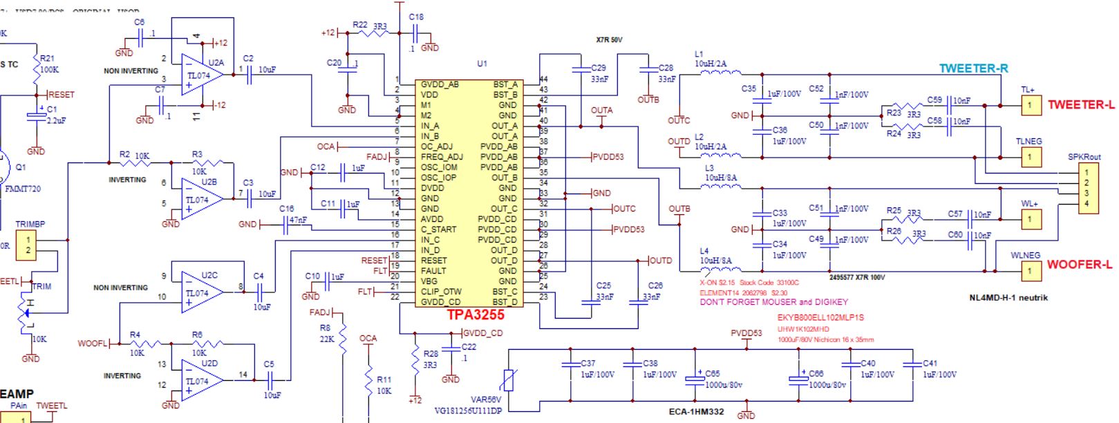
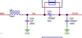
My schematic is included (part)
Any suggestions would be appreciated, specially about connecting FLT to clip and FLT as an 'or'....
Cheers all.
Julian