This thread has been locked.

If you have a related question, please click the "Ask a related question" button in the top right corner. The newly created question will be automatically linked to this question.

【TLV320ADC3101 Configuration】A very poor quality recording issue

Part Number: TLV320ADC3101-Q1
Other Parts Discussed in Thread: TLV320ADC3101,

Hi guys.

The sound quality of the recording on my board is poor. I hope you can help me see some of the reasons.

My configuration is as flows:

1. use INL2L&IN3L  IN2R&IN3R as Differential Pair, But the actual circuit is a pseudo-differential;

2. MCLK pin is connected to BCLK, so MCLK's frequency is equal to BCLK's frequency;

3. use I2S mode, sample rate(48000), wordlength(16bit);

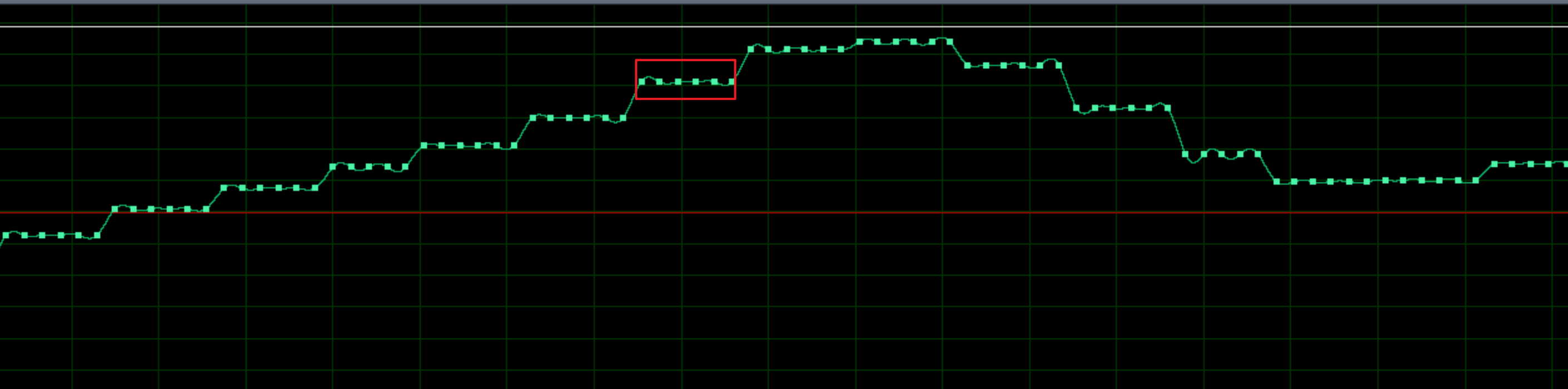
The wavefroms is as flows:


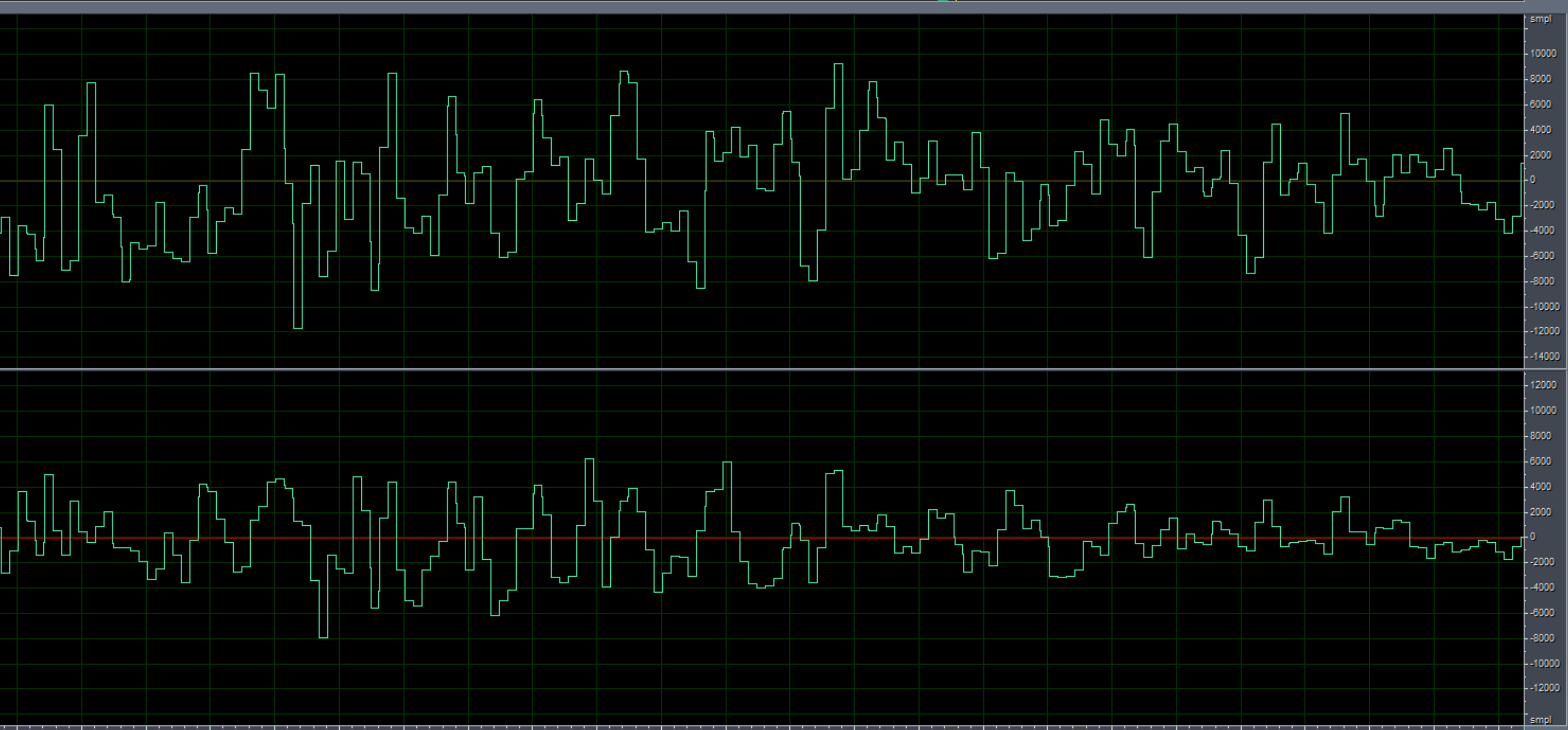
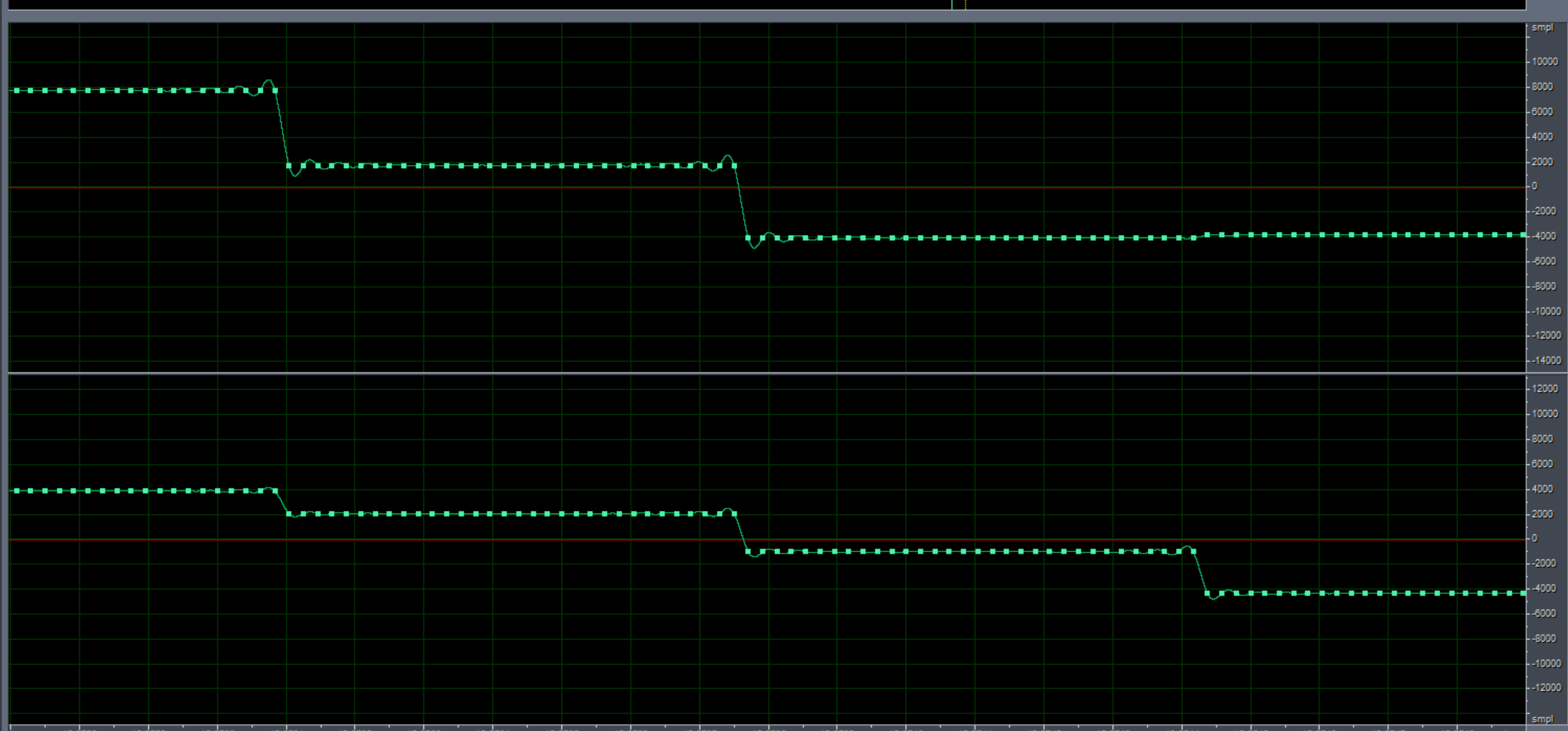
You can see that every 32 sample points will be the same range, which is very strange, and I hope you can give me some Suggestions

  • Hi Wanshu,

    Are you capturing this from an EVM or from your own board? Could you possibly share a register dump of your configuration and a schematic around TLV320ADC3101?

    Best,

    Zak

  • It's my own board, The main register configuration is as follows:

    register  value

    page0

    0x04  0x00

    0x05  0x11

    0x06 0x20

    0x07 0x00

    0x08 0x00

    0x12 0x84

    0x13 0x82

    0x14 0x80

    0x1B 0x00

    0x3D 0x01

    page1

    0x33 0x50

    0x3b 0x3f

    0x3c 0x3f

    0x34 0x3f

    0x37 0x3f

    page0

    0x51 0xc2

    0x52 0x00 

  • Things got better after I changed the following Settings:

    reg - value in page 0

    0x06  0x01

    0x12 0x81

    0x13 0x81

    0x14 0x01

    but it wasn't completely resolved

  • For the external input clock, whether need to meet >= 128fs/256fs in tlv320adc3101?

  • Hi Zak, could you please answer my questions.

  • Hi Wanshu,

    I believe you have some issues in your clock generation scheme. I see in your writes that you are configuring the PLL, but you have not enabled it. Are you intending to use the PLL or rely solely on the clock dividers? Note that the max BCLK frequency is 13MHz and your initial settings would required a much higher clock frequency than what the device supports. What is your intended MCLK/BCLK?

    I would recommend you look at the detailed design procedure in section 11.2.2. Based on your sample rate, you will use decimation filter type A and the AOSR must be a multiple of 8. It is also limited by equation 6) 2.8MHz < AOSR * 48kHz < 6.2MHz so you need an AOSR of at least 64 and no more than 128.

    Next your dividers need to be chosen to determine your ADC_CLKIN based on your AOSR and sample rate. ADC_CLKIN / (NADC x MADC x AOSR) = 48kHz

    NADC should be as large as possible but satisfy MADC x AOSR / 32 >= RC, where RC is based on the processing block you have chosen and is shown in table 5.

    Best,

    Zak

  • Hi Zak.

    Thanks for your reply. my intended MCLK and BCLK is equal to 3.072MHz and channels should be 2, So seems like I have to raise my clock frequency to solve it?

    Another question, is TLV320ADC3101-Q1 the same requirement as TLV320ADC3101?

    BRs.

    Wanshu

  • Hi Wanshu,

    Yes you either have to use the integrated PLL to generate the higher frequency clocks or use a higher frequency MCLK/BCLK to rely solely on the dividers. If you haven't used it there is atually a Clock/PLL tool inside the ADC3101EVM GUI you can use. It's under the digital settings tab in the GUI. Note to access the GUI you have to run it as an administrator. It will generate multiple options for your settings and you can determine which work best for you. If it generates PLL coefficients this means you need to use the PLL, but if it does not generate these then this means your clocks are fast enough to rely on the dividers.

    And yes, the -Q1 variant is functionally equivalent, it just goes through additional automotive qualification testing and has a higher level of reliability that is typically required in automotive applications. 

    Best,

    Zak