This thread has been locked.

If you have a related question, please click the "Ask a related question" button in the top right corner. The newly created question will be automatically linked to this question.

SE555: "Output-pulse rise/fall time"

Part Number: SE555
Other Parts Discussed in Thread: TLC555

Hello,

SE555 defines parameters "Output-pulse rise time" and "Output-pulse fall time" in its data sheet, but what exactly do they mean?

I suspect they are rising and falling times of OUT pin signal edges at thresholds 20 - 80% or 10 - 90%, for example, but my impression says the values of 100 or 200 ns look too large for the rising and falling edges. I'm wondering if they mean somewhat a propagation delay.

Best regards,
Shinichi Yokota

  • Shinichi-san,

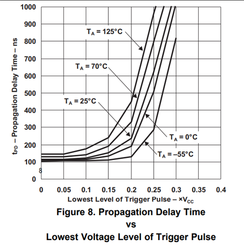
    My impression of the rise and fall times is as you described. I found in Figure 8 the description of Propagation delay vs the lowest level of the output pulse. If the low level is zero for example the propagation delay at room temp is roughly 100ns. So this tells me that the spec you are referring to has the propagation delay built in with the assumption that the trigger voltage low level is zero. 

  • Chris-san,

    Thanks for your feedback. I guess this device is too old to make a comment, but does your team have any record that can back up your assumption?

    I remember using a 555 timer IC for my hobby in my childhood. 555 timers are that old.

    Best regards,
    Shinichi Yokota

  • Shinichi-san,

    Unfortunately we don't. This device was created 10 years before I was born. 

    The propagation delays relative to the max specified frequency of 100kHz are fairly negligible. 200ns compared to 1/100kHz = 10us. 

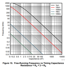
    The propagation delays really start to impact the performance at frequencies above 100kHz. My assumption with this is a comparison of the free running frequency curves from the TLC555 and the SE555. You will notice that the TLC555 product datasheet uses equations that do not use the propagation delays and then equations that consider the propagation delays. The equations that do not are for frequencies under 100kHz and these equations match the SE555 equations. 

    Note that in comparing the curves below (SE555 on the left) that the line is linear and is only specified up to 100kHz for the SE555. On the right image for the TLC555 there is curvature in the plots for both 10k and 1k for frequencies operating above 100kHz. I recently had to handle an issue running at high frequencies for the TLC555 and the equations that utilize the propagation delay form the curves for the TLC555. The simple equations without prop delays will follow the linear lines. 

    Looking at this error as a percentage of operating frequency in time is the best way to look at it.