This thread has been locked.

If you have a related question, please click the "Ask a related question" button in the top right corner. The newly created question will be automatically linked to this question.

CDCE72010 Power Supply

Other Parts Discussed in Thread: CDCE72010

Hallo together,


I want to test the CDCE72010 Jitter cleaner.

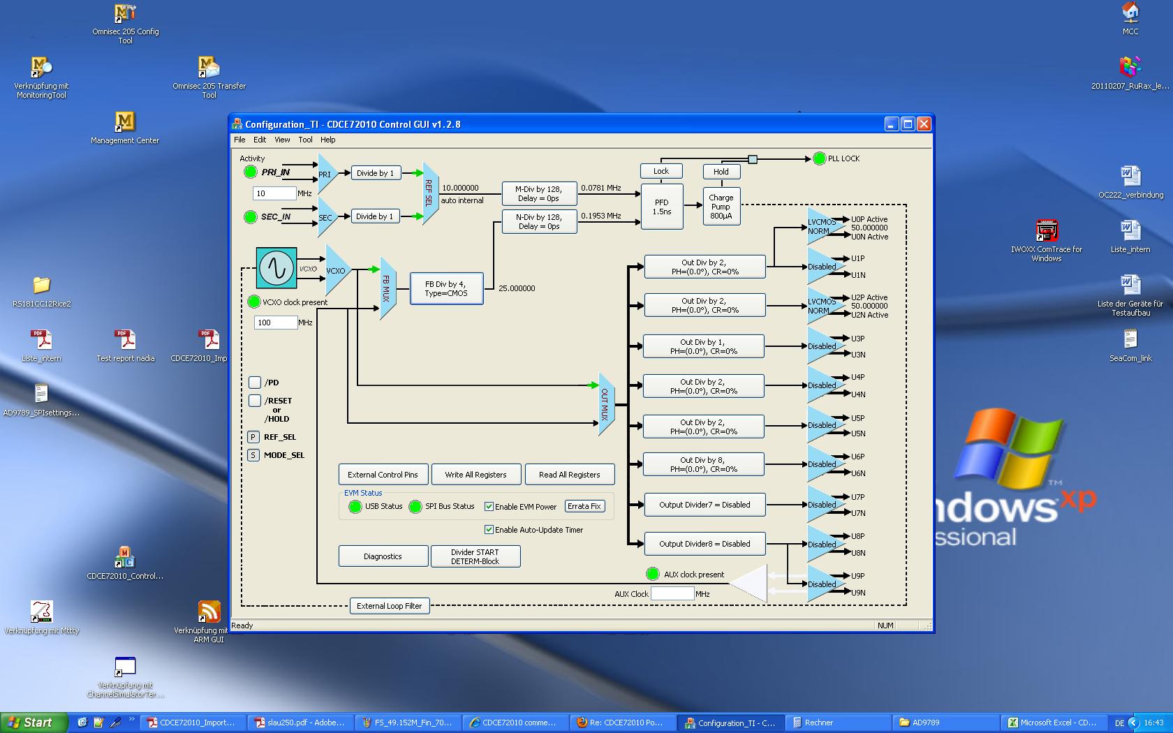
I install the GUI and before i make any configuration i notice that the board have no current circulation when i use an externel source.

In User Guide, The CDCE72010EVM can be powered from USB or external source.

so i plug 3.3V power Supply to the Board  and change the jumper Position JP_3_3 to 1-2 (3.3V Power) and nothing is happend. No LED lit or flash!!  and i see no current circulation on my switching power supply device (the same thing when i apply 5V)

so i don t know what  to do.

Please help me.


  • Hi Nadia,

    With the USB connected, click on the 'Enable EVM Power' checkbox in the GUI. It is okay to use external 3.3V Power the way you described above or use the USB for power - set the JP_3_3 jumper accordingly. The TUSB3210 controller on the board is powered by the USB and controls the LEDs. When using an external supply, make sure the current limit is set high enough - high performance clocks do use a bit of power.

    Let me know if this helps,

    Matt

  • Salut Matt,

    thank you.

    so i powerd the CDCE72010 from the USB and make my configuration.


    My configuration is follow:

    I apply only  10 MHz frequency from HP 8657B and write 100MHz for VCXO!!! not from generator.

    1/N = 10 Divider,  1/M = 2, 1/R = 1/FB = 1 so that  Phase margin is about 63

    all LVCMOS output .

    on User Guide i can write this configuration on EEPROM unlocked and disconnect USB and connect 3.3V power supply.

    My question is : No Output Signal on Specrum Analyzer !!and why no LED Lit on CDCE72010 Board!!!???

    I think the board no work on 3.3 V supply.

    Please help me


  • Please sent me a help as soon as possible.

    Thanks

  • Hi Nadia,

    I have a couple questions. Do you see an output while you are using the GUI with the USB connected? With the USB connected, do you see the PLL lock indicator in the GUI and on the EVM (LED) turn on?

    Matt

  • Dear Matt,

    I see nothing : EVM LED is OFF  and no Output Signal on Spektrum Analyzer appear

     PLL Lock lights  green on GUI.


  • Hi Nadia,

    Can you please save the settings file from the GUI and a screen shot of the GUI window? Also, let me know which type of VCO you are using.

    Best regards,

    Matt

  •  

    Hallo Matt,

    on the Board of CDCE72010 EVM  is  TOYOCOM : TCO21111with 491.152MHz .


    The Register Setting are Follow:

    Normal 0 21 false false false DE X-NONE X-NONE

    REG0=001002C0

    REG1=69800011

    REG2=01800002

    REG3=69400033

    REG4=69800004

    REG5=69800005

    REG6=690403C6

    REG7=68400117

    REG8=680C0248

    REG9=6903F049

    REG10=01FC07FA

    REG11=C081000B

    REG12=61E09F0C

    [EVM_OUTPUTS]

    PWR_EN=1

    Y0_TERM=1

    Y1_TERM=1

    Y2_TERM=1

    Y3_TERM=1

    Y4_TERM=1

    Y5_TERM=1

    Y6_TERM=1

    Y7_TERM=1

    Y8_TERM=1

    Y9_TERM=1

    MODE_SEL=1

    REF_SEL=1

    AUX_SEL=1

    RESET=0

    POWER_DOWN=0


  • Hi Nadia,

    One problem I see with the register settings is that the VCXO internal input termination needs to be enable because there are no termination resistors on the EVM. This might be why there is no signal on the device outputs.

    I see a few other problems in the setup. For example, right now the VCXO on the board is 491.52MHz, but the GUI is calculating frequencies based on the 100MHz entered.

    If you send us the desired input and output frequencies and formats, the loop bandwidth you need, and the VCXO you plan to use I can quickly generate a setup for you on Monday in our lab and send you the .ini file.

    Best regards,

    Matt 

  • Hallo Matt,


    Thank you very much for your answer.

    First question is : what you mean with VCXO internal input Termination!! which register i need to configure.

    on the GUI i can enable this parameter on > VCXO Buffer Config > input Buffer termination enabled........... Should i make any configuration on the hardware?

    What i want is :

    a singel-ended LVCMOS output signal with 49,152 MHz frequency. I use in this case the onboard VCXO and an external input REFand the 3.3 Power Supply.


  • Hi Nadia,

    Please try these settings.

     http://e2e.ti.com/cfs-file.ashx/__key/CommunityServer-Discussions-Components-Files/48/0257.new_5F00_settings.ini

    Best regards,

    Matt

  • Hi Matt,


    Thank you . It work ?!! I can see the output Signal on my spectrum Analyzer.

    But I have one last and important question.

    I want to save the configuration and work without USB, only 3.3 V Power Supply. What i should change or consider.

    I take the following Step:

    Write all register > Write to EEPROM Locked > USB cable disconnect> JP3_3 on position 1-2 (3.3V Power) > on the GUI Enable Power Uncheked

    But i see no current consumption and no LED is lighting. What i make false.


  • Hallo Matt,


    Thank you very much . All configuration Work : ). I found my Mistake.

    Super Service TI.


  • Hi Matt,


    I need your help by CDCE72010.

    Last week i save my configuration to EEPROM_Locked and i know yet , i can t change it or write a new sequence.

    Is there a way to undo this!!!???, so that i save  to EEPROM_Unlocked.

    Please tell me if yes.

    Best Regards.


    Nadia Largou


  • Hi Nadia,


    Please write me an email with your phone number so I can give you a call.

    mariajose.ferrando@ti.com