This thread has been locked.

If you have a related question, please click the "Ask a related question" button in the top right corner. The newly created question will be automatically linked to this question.

LMX2491: Lmx2491 as Adf4159 replacement

Part Number: LMX2491
Other Parts Discussed in Thread: LMX2492,

Hello.

In our designs we are using TI Dsps and also an ADI device for signal generation.

For this,  we have created a coherent system, and all components are sourced from the same clock across the board at 50Mhz.

We would like to know if with Lmx2491 or Lmx2492, we would be able to set a ramp time that is an exact multiple of the ADC sampling frequency in continuous mode (phase coherency).

From a quick look at TIcs pro sw, we do not see much control of the ramps. Is there any other tool or spreadsheet for this? Probably what we want to do is easier by directly writing to the Registers.

Please, could you give us some advice about this? We think Lmx2491 could be a perfect fit for our application.

Best regards

  • Hi Pak,

    Have you checked the LMX2491 datasheet section 8 and the LMX2492 EVM user's guide? We have put some ramp examples over there, are they something you are loop for?

    With these PLLs, once you have setup the ramp profiles, you can trigger the ramp by either hardware or software, ramping will run automatically.

  • Thank you Noel.

    I have checked documentation and also TICS pro software.

    However, TICS pro is a litle bit high level and tries to compensate ramps, so you don't have exact control.

    For example, I would like to set a ramp (or different ramps) that repeat every XX microseconds, without variation on time.

    I have read on the forum that in some modes there is a compensation or calibration that causes some jitter.

    I am looking for something simpler, where you control number of steps and increase of frequency of steps, to set a deterministic ramp. For example, with ADI tool:

    This could be helpful.

    Best regards

  • Hi Pak,

    Can you draw your ramp waveform (freq. vs time)? I can setup TICS Pro for you.

  • Thank you Noel.

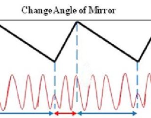
    An example could be this signal:

    For example, the long ramp side can be 560us and the short ramp 70us. The sweep could be 12kHz in both sides.

    We would use a 50MHz or 100MHz clock.

    Best Regards

  • Hi Pak,

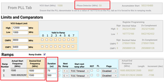
    Below configuration will sweep between 1500MHz and 1600MHz continuously once the RAMP_EN bit is checked.

    Ramp up in 70µs and ramp down in 560µs.

    Phase detector frequency is 50MHz, you can use either 50MHz or 100MHz reference clock.

    I don't understand the 12kHz requirement, is the above example something you are looking for?

  • Thank you Noel.

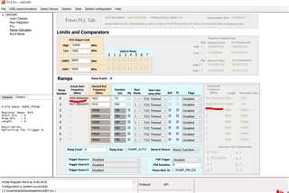
    As I see, why Frequency starts at 1600.00020265 instead of 1600?

    Would you be able to share the PLL screen?

  • Hi Pak,

    This is a round-off issue due to PLL_N = 2^24 during ramp.

    The first ramp is 100MHz in 70µs, there are 3500 sub-ramp. Each sub-ramp step size is therefore 28.5714285714285714 kHz. The actual step size will be a bit different from the mathematically value. At the end, the accumulated errors makes the actual frequency higher.

  • Thank you Noel.

    I am looking for sweeping between 1910 MHz and 1922MHz (that is the 12kHz sweep for example)

    I would like to see a PLL setup screen capture. How do you configure User_control and PLL screens?

    Is is possible to define the numer of steps instead of the time?

  • Hi Pak,

    Each sub-ramp will happen once per fpd cycle. Given fpd = 50MHz and the ramp time is 70µs, there will be 3500 sub-ramp. We can enable RAMPx_DLY bit to reduce the sub-ramp rate to once per two fpd cycles. If you want a certain number of steps, you have to pick the right combination of fpd and ramp time. 

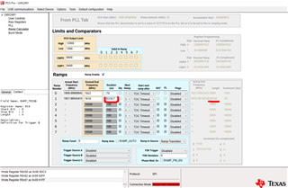
    Here is the .tcs file for sweeping between 1910 and 1922 MHz.

    lmx2491.tcs

  • Thank you Noel, I have two questions more to really understand LMX241.

    Why the initial and ending values of first ramps don't match? Shouldn't hey?

    Is it possible to set a longer ramp? For example 5ms.

    Finally, what registers are needed to be sent. Is there a source code example using an MCU and LMX241?

    Thank you

  • Hi Pak,

    The frequencies do not match because the step sizes are different in these two ramps, you have a smaller step size in RAMP1 because of longer ramp time. 

    Remember the VCO frequency will be incremented once every fpd cycle, if you need very long ramp time, you have to use a smaller phase detector frequency. In this example, you have to set fpd = 25MHz and RAMPx_DLY = 1, if you need 5ms ramp time,

    After the first Vcc power up, all the registers as shown in Raw Registers page in TICS Pro have to be programmed once. After that, program only those registers that you want to change, for example, PLL_N, if you want to change the VCO frequency.

  • Thank you Noel.

    But in the example I shared, one ramp time is exactly 8 times the other ramp, so the beginning and end should match as long the range is also dividable by the same factor.

    About the long ramp time, what is the function of RAMPx_DLY = 1?

    Is there  a C source code sample for any of TI  MCus or Dsps?

  • Hi Pak,

    Ramp up step size is 3.4285714285714285714285714285714 kHz; ramp down step size is 0.42857142857142857142857142857143 kHz. We cannot produce these frequencies in exact. There must be a round-off error. 

    RAMPx_DLY bit is used to reduce the ramp rate to once per two fpd cycles.

    I am afraid we don't have example programming code except for TICS Pro,.

  • My question is: There are 141 Registers, is it necessary to send them all?

    About the ramp size, I wonder if a mismatch between ramps will provoke a detachment between VCO and the PLL. This is what happens traditionally with PLLs.

    Or on the contrary, LMX241 will just treat these ramps independently and work without issues.

    Regards

  • Hi Pak,

    After the first Vcc power up, all the registers as shown in Raw Registers page in TICS Pro have to be programmed once. After that, program only those registers that you want to change, for example, PLL_N, if you want to change the VCO frequency.

    The frequency shown in the tool is a calculated value, the "real" frequency when you execute the ramp may not necessary be equal to the calculated value exactly. For example, after 70µs, we do not know if the frequency will be exactly equal to 1922.00000000MHz. Furthermore, the PLL/VCO does not know the amount of frequency mismatch, it will simply response to the RAMP_INC value and change its frequency accordingly. As long as the loop's response time is fast enough, you will get a gentle linear ramp without abrupt frequency change (jump).