This thread has been locked.

If you have a related question, please click the "Ask a related question" button in the top right corner. The newly created question will be automatically linked to this question.

LMK04806: Clock output on CLKout10 and CLKout11

Guru 11150 points
Part Number: LMK04806
Other Parts Discussed in Thread: USB2ANY

Hello,

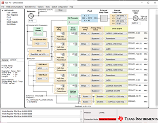
My customer set up the LMK04806 to output 61.44MHz on CLKout 10 and CLKout 11 as shown below.

The CLKout11 outputs a normal clock signal, but the CLKout10 has no output.

Please review whether there is a problem with the attached register setting.

R0 (INIT)	0x80160140
R0	0x00140100
R1	0x00140141
R2	0x00145002
R3	0x001400A3
R4	0x00140144
R5	0x00140505
R6	0x00000006
R7	0x00000007
R8	0x88000008
R9	0x55555549
R10	0xD021410A
R11	0x0401100B
R12	0x1B0C006C
R13	0x3B02802D
R14	0x1210000E
R15	0x8000800F
R16	0xC1550410
R24	0x00000058
R25	0x02C9C419
R26	0xAFA8001A
R27	0x1C05001B
R28	0x0020801C
R29	0x0080051D
R30	0x0200051E
R31	0x001F001F

Thank you.

JH

  • Hi JH,

    I don't see anything wrong with the registers. Can you have the customer check a few things:

    • Can they get an output out of other formats from CLKOUT10? For instance, can they get LVDS from CLKOUT10?
    • If they probe the pins, rather than the trace or the output connector or some other spot, do they see output? Checking for soldering issues.

    Regards,

    Derek Payne

  • Hi Derek,

    Thanks for your help.

    1. For example, if the customer changes the output format to LVCMOS (Norm/off) and LVCMOS(Inv/Off), clock signals are output from CLKout10 & 11. Is this normal operation?

    How can the customer know which output formats are available?

    2. The customer set up the LMK04806 as shown below.

    The clock signals of CLKout6, CLKout7 and CLKout8 are output differently from the settings in the GUI.

       - CLKout6 and CLKout7 : Set value - 491.52MHz / Output - 192MHz

        - CLKout9 : Set value - 3.84MHz / Output - 19.3MHz

    Is the above setting not possible?

    Could you please provide a verified example register value?

    Thanks a lot.

    JH

  • JH,

    In the image above, it shows that the connection mode for TICS Pro is "Device Not Connected". Are you using this as an example for my benefit? Or is this what the customer is providing you? This sounds like a communication error, as I can't see another way the dividers could be incorrect with one value high and the other value low. Can you please ensure that the customer has the USB2ANY connected through the UWIRE bridge, with the jumpers connected as shown?

    Regards,

    Derek Payne

  • Hi Derek,

    The TICS Pro image was received from the customer. They does not have LMK04806EVM.

    They uses TICS Pro to create the register values and test the LMK04806 operation on the custom board.

    Regards,

    JH

  • JH,

    Understood. The UWIRE interface is different from a standard SPI signal, so that would be my next guess for reasons why things would be so wildly off.

    I know that there are some special conditions for programming dividers when the value of the divide is > 25, see section 8.5.1. Is this being done?

    Are they applying a signal to the OSCin port during register programming?

    I'm also going to reach out internally to see if someone else on the clocking team with more experience with LMK04806 has ever seen something like this.

    Regards,

    Derek Payne