This thread has been locked.

If you have a related question, please click the "Ask a related question" button in the top right corner. The newly created question will be automatically linked to this question.

LMX2595EVM: SPI Clock Speed - Eval Module Communication without the Performance Board

Part Number: LMX2595EVM
Other Parts Discussed in Thread: LMX2595

I am currently trying to interface the LMX2595EVM with a custom control module of my own (created on Digilent's Arty S7-50), and I am currently having trouble communicating with the part and I think I have attributed it to the speed.

What I want to know is why is the performance board talking to the LMX2595EVM at only ~127kHz? Plus, why is there such a long gap between writes (on the order of 12ms)? The datasheet for the part lists the maximum write speed as 75MHz, as well as the minimum enable pulse width high time as 10ns -- I am operating at 50MHz with a high time of 100ns on the enable pulse width

Does anyone know what might be wrong here? Thanks

  • I just found this answer

    https://e2e.ti.com/support/clock-timing-group/clock-and-timing/f/clock-timing-forum/921224/lmx2595evm-spi-write-speed?tisearch=e2e-sitesearch&keymatch=LMX2595EVM#

    I'm going to go ahead and for the time being try this, is there any other problems I should be concerned with due to the spacing of my data words?

  • Dylan,

    As far as I know, there's nothing else to be aware of. We had to put the resistors in the SPI lines to prevent the 3.3V programmer from driving the digital inputs and damaging the device before VCC is applied. In hindsight, some kind of off-board bus enable would have been nice instead; this could have retained high speed SPI without requiring board modifications.

    Otherwise your word spacing and SPI speed should be fine.

    Regards,

    Derek Payne

  • Sounds good, thank you for the quick reply

    Do you recommend 33Ω as was suggested in that blog post, or should I aim more towards characteristic impedance and try 42Ω? I am going for 50-75MHz type speeds on this one

  • At 50-75MHz, I don't think it's going to make too much difference... there was no plan for the SPI lines on the EVM to be impedance-controlled, so they don't have a consistent characteristic impedance; the 33Ω (or 42Ω) resistor is a best-guess attempt to reduce reflections from inevitable driver and line impedance mismatch. I say as long as you're driving the signal over no more than a few inches, there isn't going to be much difference, even at maximum SPI speeds.

  • Hi Derek, I have one more question regarding the speeds:

    When I am toggling FCAL_EN to lock the VCO after changing frequency, is there a minimum recommended time between turning it off then back on again? I seem to be having trouble getting my VCO to lock when doing it manually vs. the GUI, yet I am sending the same exact commands as the GUI is

    (I am setting everything up in the GUI then switching over to manual control just for prototyping)

  • Any time you write to R0 with FCAL_EN=1, that should calibrate the VCO. Are you writing all the registers and then immediately calibrating with FCAL_EN=1? The VCO LDOs need a little time to settle after the first programming, I think the datasheet notes this in the programming sequence where you have to write FCAL_EN=1 an additional time after programming.

    Regards,

    Derek Payne

  • Basically my sequence of programming is this:

    Calibrate and set to 14GHz in the GUI, let the PLL lock (includes writing all the registers, etc.)

    Removing the ribbon cable from the LMX2595EVM and attaching my own wires to SDI, SCLK, CS, and MUXOUT

    Programming R0, R36, R37, and R39 with 0x2414, 0x0050, 0x0204, and 0x86A0

    Programming R0 with 0x241C (to get that enable cal)

    My clock is at 50MHz, and my state machine is running off that as well. My concern is that I am not giving the LMX enough time before writing to R0 again, should I toss in a delay there?

  • Hi Dylan,

    1. "Removing the ribbon cable from the LMX2595EVM and attaching my own wires to SDI, SCLK, CS, and MUXOUT". Just wanted to make sure that you have the GND of both boards connected together.

    2. "Programming R0, R36, R37, and R39 with 0x2414, 0x0050, 0x0204, and 0x86A0". You don't need to change R0 here. Simply program what do you want to change. 

    I am not clear from the dialog that were you able to problem the EVM but did not get it lock or you were not even able to program it successfully with your own programming board?

    Anyway, can you try, in bullet 2 above, instead of programming a bunch of registers, simply program R0 = 0x241D to see if you are able to powerdown the EVM?

  • Hi Noel,

    1. Yes, grounds are connected together

    2. Got it, I thought I needed to toggle R0[3] in no assist mode to get it to lock?

    I will try and just program that power down bit, it may have something to do with my custom SPI module but I can't be sure (sims look alright on my end). When I program it, it doesn't lock and powers down the output so I am thinking it has something to do with my code possibly

  • Noel/Derek

    I probed at the Clock test point pin and am seeing that my clock is still being attenuated/killed, despite me replacing the 12kΩ resistor with a 39.3Ω resistor

    The signal coming out of my controller is clean and the drive is relatively strong - any idea what might be causing this?

  • Hi Dylan,

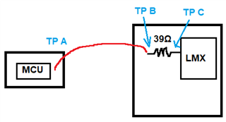
    Did you mean you've got good waveform at TP A but bad waveform at TP C? How does the signal look like at TP B?

  • TPA is good, TP C looks like the old attenuated signal, I will probe at TP B to look and see

    I am using the SCK_TP on the Eval board, I ran it without an input clock, just the 3.3V powering the LMX and saw the 50MHz clock (with a better scope albeit), I will try the full setup again with a different oscilloscope

  • The internal impedance of the eval board pins (Arty S7) was interfering with my signal drive when coupled with the 39Ω resistor, effectively killing the high frequency signal. Moving to 0Ω resistor pins while keeping the 39Ω resistors on the LMX2595 board fixed the clock, although now I have the problem of the clock swing being too big (6.7V from a LVCMOS33 driver somehow)

    Should I increase the 33Ω resistor to 50Ω to help tame this signal?

  • Hi Dylan,

    Did you mean the voltage swing at TP B is now 6.7V? If your MCU is 3.3V operated, you should not get 6.7V from it.

  • TPA, B, and C is 6.7V. I did some calculations and it appears that it could be due to my reflection coefficient (1.8x)

    Additionally, the SDI line at those test points is killed, it doesn't seem to be effectively clocking out that data.

    I am going to replace the 33Ω resistors with 0Ω resistors and communicate via the 200Ω resistor pins on the Arty - I think this will fix my problem of attenuation

  • Hi Noel,

    Replacing the 33Ω with 0Ω resistors and increasing my FPGA drive strength fixed the reflection/attenuation problems I was having

    I can now write to the FS - thank you for your help