This thread has been locked.

If you have a related question, please click the "Ask a related question" button in the top right corner. The newly created question will be automatically linked to this question.

LMX2594EVM: The LMX2594EVM is not working on the customer's application

Part Number: LMX2594EVM
Other Parts Discussed in Thread: LMK03328

Hi Team,

We have received this inquiry from our customer.

Apologize in advance as I'm not very knowledgeable in the topic. But essentially in my team we use these device to generate a GHz signal typically in the range of 4.0 - 4.5 GHz. Now, we have a pre-built panel where I can simply replace this component and all connections for power and control have already been established. And in the past whenever one of these PLL has gone bad (for whatever reason) we have simply been able to replace it with a new one and it worked as expected out of the box.

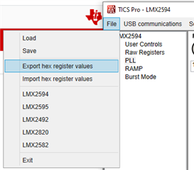
However, I recently purchased 2 of these components directly from TI (previously we had purchased from a 3rd party vendor) and this did not happen. As in, when I connected the PLL it did not respond as expected. And so I was wondering if there's any new changes for example, some initial program flashing or setup that I need to perform now (that maybe wasn't in place say a year or two go).

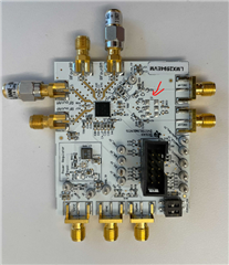
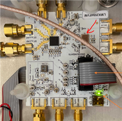
I don't see an LED turn when simply connecting a 3.3V power supply to the VCC input on the board. Previous LMX2594EVM boards due turn on an LED for power. Are other connections necessary just to make this LED turn on?

Thank you for your support!

Regards,

Danilo

  • Hi Danilo,

    As far as I know, we did not modify the chip after RTM. 

  • Hi Noel,

    Thank you for your response. I understand that the Reference Pro board is included with LMX2594EVM which allows for a USB interface with TICS PRO software and the Reference Pro board is used to generate a reference clock for LMX2594EVM.

    Can you please help us with the configuration of TICS Pro software to test the LMX2594EVM? The training video of TICS Pro I found from our website is for another device, LMK03328.

    Regards,

    Danilo

  • Hi Danilo,

    EVM setup guideline is already documented in the EVM user's guide. 

    My suggestion is, follow the user's guide instruction to make it work in the Default Mode. After that, customer can modify TICS Pro configuration according to their system need.

  • Hello Noel,

    Unfortunately I haven't been able to completely follow the steps outlined in the User Guide as I don't have all the required tools.

    Specifically:

    - A 100 MHz clock.

    Can I use the Reference Pro board that comes in the package as a clock? Alternatively, I have a Signal Generator that can go as high as 20 MHz, would it be possible to modify the user guide steps slightly to accommodate to this?

    - A phase noise analyzer.

    I currently have a network analyzer but have not been able to make this measurement. Do you have any suggestion for other common lab equipment I could use to visualize this measurement,. Maybe an oscilloscope?

    On a separate note.

    I have LMX2594EVM board that is fully-working for my setup. Is it possible to obtain the configuration of this board through the TICS Pro software and use it to program the new boards accordingly?

    If so, could you share some steps on how to do this.

    Thank you for your assistance,

    Daniel

  • Hi Daniel,

    If you just want to see if the EVM is functioning but not going to have a precise phase noise measurement, as it is already shown in the EVM user's guide, you can use Reference PRO's 100MHz output clock as the reference clock to LMX2594EVM. You can use the spectrum analyzer to see if the EVM will lock. EVM Default Mode output frequency is 7GHz, if your test equipment cannot support this frequency, in TICS Pro, change the Channel Divider value to reduce output frequency to suit your test equipment.

    After you have done TICS Pro configuration, you can export all the register settings in a text file.

  • Hello Noel, 

    Thank you for your assistance and my apologies for not noticing this earlier. But it seems like there is a hardware difference between my "working" EVM and the newly purchased ones.

    The new boards are missing a VC-708 Differential Output Crystal Oscillator VC-708 February 07 2014.indd (vectron.com). See images below.

    New "not working":

    Old "working":

    I'm not familiar with this component at the moment, do you know anything about it?

    And could you confirm whether this is something that TI used to provide with previous versions of the EVM.

    Regards,

    Daniel

  • Hi Daniel,

    Old EVM came with an on-board 100MHz XO. Since this XO is EOL, new EVM will not have this XO. In the (new) EVM user's guide, we are asking to use the 100MHz output clock from Reference PRO as the reference clock to the EVM. 

  • I understand Noel.

    Do you know if it's possible to get an old EVM (with an on-board 100MHz XO)? Although not manufactured anymore, maybe TI still has some old models laying around or would be willing to assemble some with remaining VC-708 oscillators.

    Also, could you let me know if there are any other changes that have been made to the EVM boards recently? If it's only the missing XO, would it be a possible solution for me to obtain the exact same model of XO and solder it in the appropriate position. Would the EVM work as expected with this?

    As always, I appreciate your support.

    Daniel

  • Hi Daniel,

    I cannot agree with your request.

    Let me ask you, if you follow (new) EVM user's guide to setup the (new) EVM, are you able to get it locked? The XO is not a hurdle, the new EVM has been configured for an external clock source, it could be a signal generator or Reference PRO.