This thread has been locked.

If you have a related question, please click the "Ask a related question" button in the top right corner. The newly created question will be automatically linked to this question.

LMX2592: How to maximize output power?

Part Number: LMX2592
Other Parts Discussed in Thread: LMX2694-EP

Greetings,

Your colleague, Art Mecina in the TI Customer Support, suggested that we reach out on this forum for technical support for our question regarding the output power of the LMX2592.

We are designing a FDD/TDD custom radio front end operating up to 7.125 GHz, LO is appx 8.3 - 8.6 GHz and we are using the LMX2592. We will be driving several mixers, and we need to maximize the output power. We have 6 mixers that need LO.

The ref circuit is using 50 ohm termination, and on top of that leaving one side unused, wasting a lot of power. The user data sheet suggest using an inductor with resonance at the desired frequency. In either config, we want to use a balun (LC type) and convert the diff to SE, then it will be fed to 2 layers of splitters each with 4 dB of loss, give or take.

Question is: Using inductors, what is the impedance of the outputs, and how do we match it to a 50 ohm splitter (going from diff-SE)? If we use the 50 ohm termination, I assume we can at least get 3dB more power by using a 100:50 ohm balun (LC type or other) to get more power. Can you please advise on either option?

Thank you,

Andreas Gluck

  • Hi Andreas,

    From Figure 12 of the datasheet, at 8GHz output and with 50Ω pull-up, the output power is around 3dBm. If you have a balun to combine the power from both output pins, you should get 6dBm out from the balun, is it sufficient to your system?

    It is hard to tell the output impedance, it varies with the pull-up component. We have looked into this on a different device having similar output buffer structure, we came up with some suggestions in LMX2694-EP datasheet. Please check section 8.1.4 for details.

  • Thanks . Combining the output using a balun while keeping the 50 ohm pull-ups helps, and that was a backup plan, but hoped there was further information on using inductive pull-ups and then just match it to 100 ohm diff at our LO frequency (does not need to be wideband, only need 300 MHz of range), then use a balun to convert to single ended before feeding the splitters/mixers that follows. I would imagine one could easily simulate this, just very cumbersome to measure the impedance with the LO running (unless it can be disabled for measuring the output buffer only???)?

  • Hi Andreas,

    Right, simulation is better than measurement at these frequencies, however, we don't have a RF simulation model for this part.

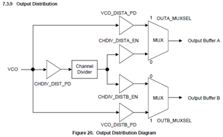
    If you were to measure the buffer output impedance without enabling the internal VCO, you can set R48[9] = 0, this will turn off the LDO for the VCO. Furthermore, disable the VCO path by setting the following registers.

  • Hi ,

    Thank you for the info, that sounds promising, especially if we can measure the output impedance with VCO disabled. I think we'll plan for inductor pullups, followed by series caps. Then we can make a real diff impedance, from there use an LC narrow band balun to convert to 50 ohm single ended.