Hi TI expert,
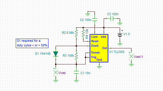
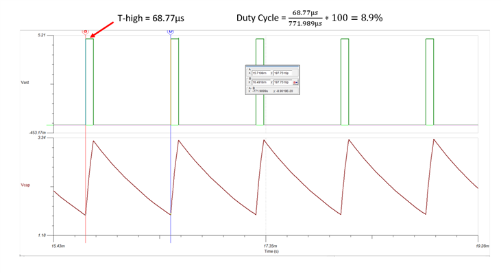
Would like to generate ~1k 8% duty PWM, use schematic below, please help check if it works.
BTW, do we need to add load resistor 8.06k between OUT to GND?
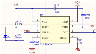
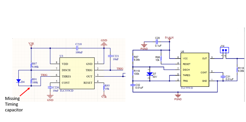
Reference circuit from TPS53681-EVM, page 11:
Using the TPS53681EVM (ti.com)

Hi TI expert,
Would like to generate ~1k 8% duty PWM, use schematic below, please help check if it works.
BTW, do we need to add load resistor 8.06k between OUT to GND?
Reference circuit from TPS53681-EVM, page 11:
Using the TPS53681EVM (ti.com)