This thread has been locked.

If you have a related question, please click the "Ask a related question" button in the top right corner. The newly created question will be automatically linked to this question.

LMX2594: Effects of using OSC_2X with non 50% duty cycle reference input?

Part Number: LMX2594

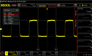
I am using the LMX2594 in integer mode with a 10MHz reference using the OSC_2X function to achieve a 20MHz PFD. I have an amplifier for the 10MHz reference preceding the LMX2594 reference input that does a good job of increasing the slew rate and squaring up the signal, however the duty cycle is not exactly 50%, it is closer to 47%, waveform picture attached of amplified 10MHz reference. What effects can I expect to see from this non-50% duty cycle reference using the OSC_2X function? 

  • Hi David,

    OSC_2x uses both the rising and falling edges of the reference clock to trigger phase detector. As a result, if the duty cycle is not close to 50%, it appears that the reference is not stable, this instability will carry forward to the output of the synthesizer. 47% is not bad, I don't expect there is big impact to the performance of synthesizer output.

  • Noel,

    Thanks for the reply, I was hoping this slightly below 50% duty cycle would still be acceptable, sounds like you think it will be. I will be gathering some test data this afternoon or tomorrow using this reference setup and will reply here again if I see any issues. Thanks.

  • Noel,

    I have conducted some testing on my board that is using two LMX2594's. Each LMX2594 appears to have a similar issue when using the OSC_2X function with a 10MHz input. Using the OSC_2X to achieve a 20MHz PFD causes some very significant -30dBc sideband spurs offset at 10MHz from the carrier, which the PLLatinum Sim software does not predict, it predicts spurs at 20MHz offset from the carrier in the -70dBc range. Re-programming the synth without using the OSC_2X function and keeping the PFD at 10MHz drops these sideband 10MHz spurs to around -60dBc. I have attached spectrum analyzer screen grabs of both synthesizers with and without using the OSC_2X function. Please advise is this performance is what you expect or what we can do to eliminate these 10MHz sideband spurs while using the OSC_2X function. Thanks.

  • Hi David,

    I think the spurs is created by the 2x. if you change the output frequency to 14GHz, i.e. direct VCO output, I guess the big spurs will move to 20MHz offset. 

    Would you please check if there is improvement if:

    - after VCO is locked, write R2 again with R2[10] = 0. This will stop the state machine clock, which is required for VCO calibration.

    - reduce charge pump current, this will reduce the loop bandwidth and therefore reduce spurs

  • Noel,

    We did as you suggested, writing R2 again after VCO was locked with R2[10]=0 had no effect at all on these spurs. Reducing the charge pump current had minimal effect, perhaps a ~2dBc improvement. Do you have any other ideas or suggestions?

  • Hi David,

    I checked the register design file, it doesn't seem to have something we can use to tweak the spurs.

    Can you live with 10MHz fpd? If not, what is the loop bandwidth right now? Let's see if we can tweak the loop filter to reduce the spurs.

  • Noel,

    I think we're going to have to live with the 10MHz PFD for now even though the phase noise gets worse, we can't live with -30dBc 10MHz spurs...

    The original loop filter design using the OSC_2X and having a 20MHz PFD, with 15mA charge pump is 145kHz bandwidth and 80deg phase margin. Changing to a 10MHz PFD, keeping this loop filter the same and keeping the charge pump current at 15mA, the loop bandwidth is 68kHz and 84deg phase margin. These loop bandwidths and phase margins are from TI PLLatinum Sim software. In reality I would like to increase the loop bandwidth with the 10MHz PFD to try to improve the phase noise performance.

    Reducing the charge pump current effectively reduces the loop bandwidth, which we already tried and saw very little improvement. I don't think it's worth the effort to tweak the filter components in hopes it will reduce these spurs 30dB, if it did the bandwidth would be so narrow that the phase noise would be horrendous.

    I still don't understand why there are 10MHz spurs at all when the PFD is 20MHz, you had mentioned that if we were to set the output to the direct VCO output that they would be at 20MHz, but this isn't true. Look at the previous plots I posted of the 11GHz output, it has these 10MHz spurs and it is the direct VCO output, not divided down.

  • Hi David,

    I still has restriction for lab access, otherwise I would like to verify this in the lab.

    OK, if you can live with 10MHz fpd, that is great. I did a quick loop filter design for 1xxkHz loop bandwidth, hopefully you will find it useful.

    https://e2e.ti.com/cfs-file/__key/communityserver-discussions-components-files/48/8270.e2e.sim