This thread has been locked.
If you have a related question, please click the "Ask a related question" button in the top right corner. The newly created question will be automatically linked to this question.
Dear team
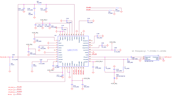
There is a good news that we design in LMX2595 in customer's new project.
Could you help to review the schematic?
Many thanks
Denny
Hi Denny,
If RFoutB is not used, we can leave the pins floating, no 50Ω shunt resistors are needed.
when they do the pcb layout, put C189 close to CPout pin; C191 close to Vtune pin.
With inductor pull-up, the output impedance will be far from 50Ω, I am not sure whether we can get normal expectation from the balun. As datasheet section 7.3.9 suggested, we recommend add a resistive pad after the output in order to get a better impedance matching.
Hi Noel
Thanks your recommend.
In customer's design RF outputs(Pin 22,23,18,19) as a single ended, How to design this outputs RFOUTAM, RFOUTAP RFOUTBP, RFOUTBM (Pin 22,23,18,19) to single ended ?
they need high power output.
Many thanks
Denny
Hi Denny,
suggest read LMX2694-EP datasheet, section 8.1.4 and 8.1.5, we have more information on the output pull-up.