This thread has been locked.

If you have a related question, please click the "Ask a related question" button in the top right corner. The newly created question will be automatically linked to this question.

Where to place Termination: AC coupled LVPECL CDCLVP1102

Other Parts Discussed in Thread: CDCLVP1204, CDCLVP1102

I am using the CDCLVP1102 (same family as the CDCLVP1204) to drive PCIexpress 100MHz reference to the input clock pins of Xilinx Virtex6 device.  I have two questions:

  1. Where should I locate the AC coupling caps; near the source or near the target?   
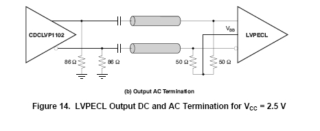
  2. Are the 50ohm Terminations after the AC caps shown in the Figure 14 of the data sheet needed for the CDCLVP part to be correctly terminated or only show there with the assumption that the next input device needs them to center the Common mode voltage to Vref?

Here are a few images from the respective data sheets.

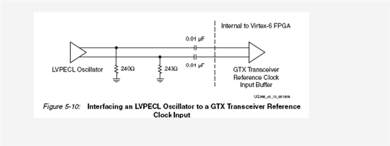
Xilinx requires AC coupled inputs as shown here.
The CDCLVP1102 data sheet shows:
 

 Thanks, Al...

  • Al,

    the AC coupling cap location is generally a don't care, as it's not impacting the transmission line impedance. If you have a system with plugging components, you may want to put it on the receiver side, but if you design one board with both TX and RX, just place it anywhere you like.

    The CDCLVP1102 does require proper input termination and biasing, as the input does not incorporate the termination resistors. Therefore, we recommend to use a Thevening termination (CDCLVP1102 data sheet figure 7) or use the termination as you show in Figure 14 in your original post (e.g. 2x50Ω with centertap to VAC_REF, which is output on pin #8 of the device).

    Best regards, Fritz


  • Fritz,

    Is there any advantage or disadvantage to using the  2x50Ω with centertap to VAC_REF solution instead of the Thevenin EQ using the external 2.5V?  Would using the VAC_REF have any noise benefit?

    I notice the data sheet spec for VAC_REF is given for a 2mA load.  With the two 2x50Ω solution will the input bias be drawing much more than that?

    Thanks, Al...

  • Al, I am sorry for taking so long to respond ...

    The differences between both schemes are small:

    The advantage of using a 2x50Ω with centertap biased is that a resistor missmatch doesn't cause any differential offset between N and P input. This will be best for maintining duty cycle and lowest jitter. I personally prefer this option. To terminate the common mode noise well, you would want to secure a good AC path from the centerpath to GND. This can be done easily, by adding a cap between centertap and GND.

    VAC_REF will only need to bias this point. At powerup, the AC coupling caps and the cap between centertap and GND are discharged. Therefore, at power up it will take some time to charge these components. The Thenvening termination is quicker to get this job done. However, as long as you are ok to wait for a few us or ms before the system is running with best phase noise/jitter performance, you are probably better of using 2x50Ω topology than using the Thevening approach.

    There is no current flow out of VAC_REF after the capacitors are properly biased. Hence the 2mA are only a limitation at startup.

    Hope all is well, best regards, Fritz

  • Thanks Fritz.

    I will use the 2x50 and Vref Center tap solution.

    Al...

  • Hello Alfred,

    after further review, we detected an issue of my previous recommendation in the case of 2.5V supply, because the VAC_REF output spec could violate the VICM input common mode spec.

    VAC_REF(min)=VCC-1.6V: for VCC=2.375V the VAC_REF(min) output voltage can be as low as 0.775V.

    The VICM(min) requirement however is 1.0V.


    Therefore, for Vcc=2.5V operation, we recommend using thevening termination or generating the centertap voltage by an external reference voltage (e.g. a resistor divider).

    For Vcc=3.3V, it is ok to connect VAC_REF directly to the centerpad.


    I hope this will not cause problems to your design.

    Best regards, Fritz

  • Thanks Fritz,

    I will use an external reference to create the centertap voltage instead.

    Al...