Other Parts Discussed in Thread: LMX2594
Hello,
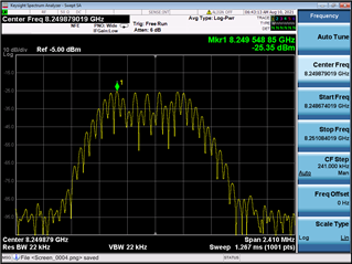
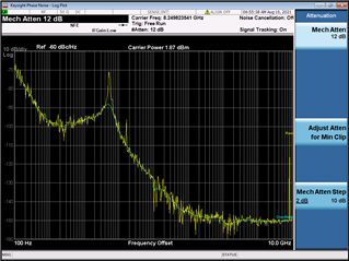
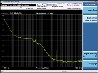
I have the following problem that occurs when I have two PLL chips on one PCB (4 layer, Rogers 4003). The two PLLs are controlled via a µC that writes all the registers to default settings. The µC first starts PLL1 and then PLL2. Both PLLs are running at 8.25 GHz and there is an LED for each PLLs' lock detect output, that are both on (= PLL locked). Looking on a spectrum analyzer the RF output of the PLLs does not look very convincing (see the pictures below). When I switch the PSU of the PCB off and on again, the output may look different (like anyone of the pics below), but never stable.
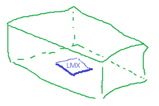
The PLL chips are physically separated by a distance of roughly 50 mm and the isolation between the RF outputs is > 60 dB. When only one PLL is activated and the other one is deactivated (CE = 0) the problem does not occur. The two PLLs share a common 100 MHz reference oscillator.
The same problem also occured using the LMX2594 on a different board.
Dou you have any idea what could cause this issue and what could be done to avoid it?
Many thanks!
Joachim