This thread has been locked.

If you have a related question, please click the "Ask a related question" button in the top right corner. The newly created question will be automatically linked to this question.

LMX2491: Start Ramp Fail randomly

Part Number: LMX2491

Hi Team,

I have a start ramp failure issue, which occurs randomly. I dumped the register just before the ramp command send. I find it seems when the failure occurs, the CPM_FLAGH in R31 is set. My question is: if this bit is set, will it block the PLL to start frequency ramp?

The other registers are no difference between the success one and failure one.

Thanks and Best Regards

Dong 

  • Hi There,

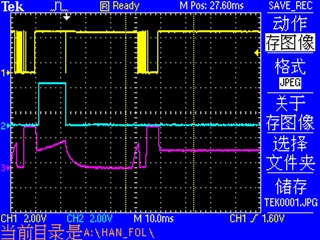
    I measured the CPOUT voltage, here is the capture:

    Channel 1: LE signal. To indicate the config period of LMX2491

    Channel 2: Trig2 signal. I configed this signal to indicate the ramp period

    Channel 3: CPOUT signal. 

    The capture shows a good case and a bad case. It seems CPOUT does not act properly in bad case. Any idea what could cause this?

    Best Regards

    Dong

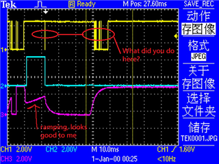
  • I saw majority failure belong to below capture:

    Any resister I could check to narrow down the issue?

    Best Regards

    Dong

  • Hi Dong,

    Did you mean after ramping, occasionally, you were not able to program the PLL to lock?

    What did you do after ramping?

  • Hi Noel,

    between the red circles, I powered off LMX2491 and also the RF chip to save power.  Then do the data process. My software flow is like: power on RF chip --> power on LMX2491 --> config LMX2491 --> start ramp --> start data sampling --> stop data data samping --> power off RF chip --> power off LMX2491 --> start data process --> repeat.

    I find this issue may be related to my program sequence: when I power on LMX2491, I also enabled CE signal, then I do the LMX2491 program. I program LMX2491 several times, each time for different register groups.  Now I changed to: power on LMX2491, but keep CE low (disable),  then I do the LMX2491 program, after program, I enable CE. Now the issue seems gone. Need to do longer time test to be sure.

    How do you think this new flow?

    Thanks and Best Regards

    Dong

  • Hi Dong,

    Do you have a large RC filter at the CE pin? 

    When CE = 0, we can still program the chip but it will not response to the new written register values until CE =1 again. 

  • Hi Noel,

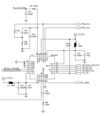
    sorry for late response. Something wrong with my email notification.  Here is my schematic. I saw RC filter at CE pin. With the current flow, I see now the SW runs pretty stable. 

    Best Regards

    Dong

  • Hi Dong,

    In your schematic, there is no RC filter at the CE pin, do you have the problem or not?

  • Hi Noel,

    For the moment, seems the software running well with the flow: program the chip first, then make CE=1. So no problem any more. Threads could be closed.

    Thanks and Best Regards

    Dong