This thread has been locked.

If you have a related question, please click the "Ask a related question" button in the top right corner. The newly created question will be automatically linked to this question.

TICSPRO-SW: Generation of register set values

Part Number: TICSPRO-SW
Other Parts Discussed in Thread: LMX2594, LMK04208

Hi team,

I got a question from customer.

"I need to generate register set values for specifications i.e. reference clock=245.76 MHz and sampling rate=3.93216 Ghz .

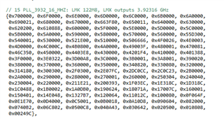
With the reference of register values provided in the example code of SDK I am able to generate and match the register values for specification i.e. reference clock=122.88 Mhz and sampling rate =3.93216 GHz.

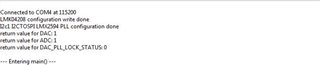
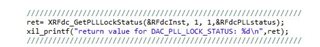
With the register values generated for 245.76 Mhz and sampling rate 3.93216 Ghz I am not getting any of the DAC's output on the spectrum analyser.

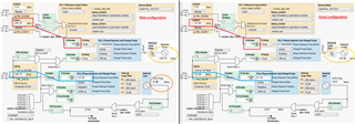
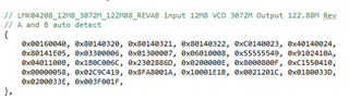
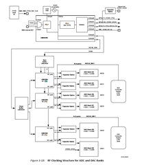
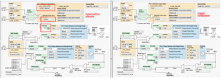
I am sharing the screenshots of LMK04208 and LMX2594 configurations and register set values generated along with this post.

Kindly see to it and correct me wherever I am going wrong."

attachments.zip

Thank you very much for your help.

Best regards,

  • Hi Zhonghui,

    could you please clarify: the system that you are looking at is working fine, when using the sample configs with 122.88MHz reference. But if changing that register settings to 245.76MHz reference then the DAC does not work?

    If changing the reference to 245.76MHz, did you check if the LMK04802 and LMX2594 does output the correct frequencies? Are the PLLs locked?

    regards,

    Julian

  • Hi Julian,

    Thank you for your help.

    Actually I am working with ZCU111 Ultrascale+RFSOC board and I yes when I tried with register values provided in the example SDK C code for reference clock=122.88 mhz and sampling rate 3.93216 ghz the DAC are giving output on spectrum analyzer as desired but when I am trying to generate the register set values for reference clock=245.76 mhz and sampling rate =3.93216ghz using TICS pro software , the register values generated (as shared previously in the screenshots and text file) is not producing any of the DAC's output on spectrum analyzer. I just wanted to know whether the configurations been set by me are correct or not? Kindly tell me how to check whether both the PLL's are locked or not? 

    As per the register values generated using TICS pro software for reference clock=245.76 mhz and sampling rate=3.93216Ghz the two PLL's are not getting locked as shown in the screenshots I am sharing along with this thread.
    Kindly tell how can I proceed further.


    Thanks and regards,

  • Hi Zhonghui,

    in the LMK04208 I see that the VCXO frequency was updated to 245.76MHz. I think that happened when you updated the CLKin1 frequency.

    This caused that the PLL1 is likely not locked. 

    Also you selected CLKin0 as reference: 

    Since this is still set to 12.8MHz the calculation for the R and N divider will be wrong.

    For the LMX2594 you want to toggle the FCAL_EN bit 

    regards,

    Julian

  • Hi Julian,

    Thank you for your time.

    In LMK04208 I had set clkin_0 as 12.8 Mhz because ZCU111 ZynqUltrascale+RFSOC board has only 12.8 Mhz frequency as its TCXO frequency. Due to the same reason I had selected clock input for PLL1 as clk_in0. I am sharing the screenshot from zcu111 user guide for your reference.
    Kindly see to it and guide.

    ZCU111 Evaluation Board User Guide (UG1271).pdf

    Additionally I tried with generating the register set values for 122.88mhz using TICS Pro by keeping this clkin_0 at 12.8 mhz and selecting clkin_0 and these register set values are matching with the values present in the example C code in SDK for RF Data Converter.

    Best regards,

  • Hi Zhonghui,

    I will pick up the support to this post.

    Would you do me a favor to send me the TICS Pro .tcs files for both good (ref = 122.88MHz) and bad (ref = 245.76MHz) configurations so that I can quickly identify what may be causing the problem? Thank you.

  • Hi Fung,

    Thank you for your help.

    I am sharing the zipped folder containing .tcs files for both good(ref_clk=122.88mhz) and bad(ref_clk=245.76mhz) of both the PLL's i.e. LMX04208 and LMK2594.

    Kindly see to it and correct me whenever I am wrong.

    TCS_FILES.zip

    Thanks again.

    Best regards,

  • Hi Zhonghui,

    couples of issue with the LMK device configuration.

    PLL1:

    Your configuration has selected CLKin0 (12.8MHz) as the reference and the fpd is just 106.6667kHz. If CLKin0 does not exist, CLKin1 will be automatically selected but then the PLL will not lock unless you change the N-divider accordingly.

    VCXO frequency should be identical in both configurations.

    PLL2:

    VCO frequency cannot be higher than 3072MHz.

    In LMX2594, with 245.76MHz reference clock, you should either increase the ACAL_CMP_DLY value to 12 or above or change CAL_CLK_DIV to "Div4, Fosc <= 800MHz".

    What were the original LMK and LMX device configuration in the ZCU111 board?

  • Hi Fung,

    Thank you for your time.

    I am sharing the screenshot of LMX and LMK configurations as given in the ZCU111 user guide as shared previously along with the register set values provided in the c code of SDK.

    Kindly see to it and suggest.

    Best regards,

  • Hi Zhonghui,

    The above shown what need to be change in order to use CLKin1 as reference.

    Attached below are the .tcs file for both the original LMK configuration and the modified configuration.

    lmk-original.tcsCLKin1 reference.tcs

  • Hi Fung,

    Thank you for your help.

    I checked with the CLKin1refrence .tcs file provided by you but I have few doubts if you can clarify.
    a) ZCU111 board TCXO Frequency=12.8 MHZ that's why I had selected Clkin0 in my original configuration. Why did you change it to CLKin1(245.76 MHz)?
    b) With this configuration also Clkout4 frequency is still 122.88 MHZ which should be 245.76 MHZ so that I can provide it to LMX2594 to generate register set values for sampling rate equal to 3.93216 GHz.

    Kindly clarify my above doubts.
    My requirement is generating register set values for reference clock=122.88 MHZ and sampling rate=3.93216 GHZ.

    Since the Clockout4 frequency (which is going as a reference clock to LMX2594) generated is always 122.88 MHZ but my requirement is to generate 245.76 MHZ as clockout4 which goes as an input to LMX2594.
    Is there any way to generate 245.76 MHZ frequency as clockout4?
    Kindly resolve this query.


    Best Regards,

  • Hi Zhonghui,

    CLKin0 or CLKin1 is your choice, I just gave you an example what need to be changed for a 245.76MHz reference clock. 

    here is the .tcs for 245.76MHz input and output.

    lmk24576.tcs