This thread has been locked.

If you have a related question, please click the "Ask a related question" button in the top right corner. The newly created question will be automatically linked to this question.

LMK05028: Configure LMK05028 so that it generates 644.53125MHz clock from IN3[10Mhz] input available from GPS

Part Number: LMK05028

Hi:

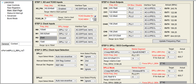
I am working on the Intel S10 SX SoC Dev Kit . LMK05028 chip is mounted on the board. The TCX0_IN is not driven by any clock. The IN3 is driven by 10Mhz from GPS. My requirement is that OUT7[644.53125Mhz], OUT5[390.625Mhz] should be generated from GPS 10Mhz as reference .The OUT5 and OUT7 are connected to FPGA. The OUT7 clock is the reference clock for the MAC inside FPGA.

DPLL1 and DPLL2 priority of clock is same. 10Mhz[IN3] has highest priority.

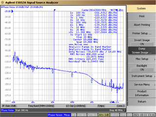
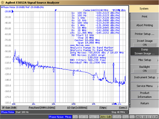
I have configured TISC Pro with below configuration. We are not getting required output that is 644.53125Mhz instead we are getting 644.46Mhz. And OUT5 if I configure 390.625Mhz actual frequency column in GUI become zero. Could you please guide me to get the OUT7 and OUT5 with proper output and frequency in sync with GPS 10Mhz.

  • Hello Neeraj,

    Can you please provide me with the tcs file of your configuration? Once I have received it, I will be better able to assist you.

    Regards,

    Kia Rahbar

  • Hi:

    This is the configuration which i am using. Attaching the .tcs file. Please help me in resolving the issue.

    LMK_644_OUT7_390_OUT5_10Mhz_IN3.tcs

    Regards,

    Neeraj G B

  • Also we are getting "Run script cancelled. MATLAB Runtime R2015b" not found when we run Step6: Run script, with .tcs file attached

    LMK05028_MATLAB_NF

  • Hi Neeraj,

    Thank you for providing the file. Kia will look into your configuration further.

    Regarding the MATLAB message, you must install MATLAB R2015b v9.0 64-bit to use the "Run Script" in the Main: Start Page. The installation is found at https://www.mathworks.com/products/compiler/matlab-runtime.html

    Regards,

    Jennifer

  • Hello Neeraj,

    The reason OUT5's frequency goes to zero is because you are attempting to have a 390.625 MHz clock and 644.53125 MHz clock come from the same PLL. Since there is no common multiple of the two frequencies, the 390.625 MHz gets set to 0. Please change your clock outputs to look like below:

    Please note I moved the 390.625 MHz clock to OUT0 because OUT[0:3] bank requires at least 1 clock from PLL2 for the DPLL calculations to occur.

    The reason OUT7's frequency is not locking to 644.53125 MHz is most likely due to the DPLL1 not locking. I have preformed the run script calculations for the DPLLs, so now the frequencies should be locking to their target values.

    Here is an updated tcs file with the changes I discussed above:

     6175.LMK_644_OUT7_390_OUT5_10Mhz_IN3.tcs

    Please load this file into your TICS Pro and preform a soft-reset chip (as highlighted below).


    Once you have completed this process, both frequencies should be locked to their target values.

    Regards,

    Kia Rahbar

  • Hi Kia:

    We have checked the outputs OUT7:644.53125Mhz and OUT0:390.625Mhz. We are not getting accurate 644.53125Mhz its around 644.46Mhz we are getting. So due to that ATX PLL is not getting locked and PHY link up only we are not getting.

  • Hello Neeraj,

    First, check the status page and ensure the LOL_PLL1, LOPL_DPLL1, and LOFL_DPLL1 are not set. If they are cleared as shown below, then the issue is not due to the DPLL being unlocked.

    If the above controls are cleared, then it appears that your frequency is 110545.45454 ppb off its target value. To remove this ppb error, you can enable the DCO mode shown in the image below and program the frequency step size to the target ppb shift required to shift the output frequency to its target value. Once you have written to the Freq. Step Size control, the FDEV will be automatically calculated. Then you can use the Incr/Decr buttons to shift the frequency.

    Please note you also have the option to preform the Incr/Decr via registers or GPIO.

    Regards,

    Kia Rahbar

  • Hi Kia:

    Status of LOL_PLL1, LOPL_DPLL1, and LOFL_DPLL1 and HLDOVR1 are set.

  • Hello Neeraj,

    This means your DPLLs are not locking, thus leading to the inaccuracy in output frequency. Once you get the DPLL to lock then the outputs will be exactly 644.53125 MHz and 390.625 MHz.

    The first step to ensure the DPLL is locking is to make sure a 10 MHz signal is actually being inputted into IN3. 

    Then, make sure the correct clock input interface type is selected for the way you are providing the input to the device.

    If that is not the issue then click update frequency plan and then click the run script button to calculate the appropriate DPLL settings. 

    Once the calculations are complete press the soft-reset chip and then make sure the DPLL status bits are no longer high on the status page.

    Regards,

    Kia Rahbar

  • Hi Kia:

    As you suggested i changed the interface type to HCSL and i am able to get lock of LOFL_DPLL1 and LOFL_DPLL2.

    Since Phase is not locked. DPLL1 and DPLL2 are still in Holdover mode.

    So when reading registers i am seeing LOPL_DPLL1,LOPL_DPLL1 and HLDOVR2 are set.

    Attaching the configuration file

    6175.LMK_644_OUT7_390_OUT5_10Mhz_IN3_updated.tcs

  • Hello Neeraj,

    I believe I have found the issue. It appears the device is having difficulties detecting your reference. To have the reference be detected and the DPLLs to lock properly, I disabled the frequency detect threshold for the inputs as shown below.

    Once I disabled these thresholds, I was able to get the DPLL to lock and have the device properly output your target frequencies.

    Here is the tcs file of the configuration I used to get proper output frequencies:

     6175.LMK_644_OUT7_390_OUT5_10Mhz_IN3_updated_by_TI.tcs

    Please load this file into your TICS Pro, then press soft-reset chip and then everything should be working properly.

    For your reference, here are the output frequencies I received with this configuration:

    Before using this method, ensure that your 10 MHz reference is stable and locked to 10 MHz.

    Regards,

    Kia Rahbar