


Part Number: LMK05318B
Other Parts Discussed in Thread: , LMK05318
Hello Team,
Please can you help me to solve an issue with LMK05318B ?
We intend to use the circuit for cleaning noisy clock signal at 10MHz recovered at the end of a very long transmission. The circuit with it's analog PLL and the BAW VCO should be as a very good solution for that as described in the application report SNAA326.
For evaluation, I've got a LMK05318BEVM board with TICS pro firmware v1.7.2.0
Through the GUI:
DPLL is disabled in order to use AnalogPLL 1 only.
XO is set to 10MHz, single ended interface and I connect a 10MHz 0dBm signal to XO connector.
Outputs are set for 10MHz in setting output Frequency plan and I can see the 10MHz signal on all activated output.
With the following configuration, Status0 LED are set on and off following the XO Input Loss of Signal, but I can’t find any solution to indicate PLL1 Lock Detected with status1 LED
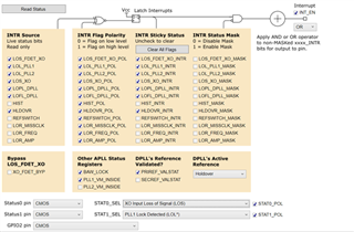
I’ve tried to change the Raw registers but without any success.
In the 0xD register, the bits 2 (LOL_PLL1) et 4 (LOS_FDET_XO) are going to 1 when the I cut the 10MHz signal on XO, but without any change on status1 which stays at 1
When I change the frequency of the generator connected to XO, these bits remain high, this should indicate that PLL1 stays locked, whatever the frequency applied on XO connector ?
Notice that in all configurations and changes the signal remains present and stable at 10MHz on the activated output
Thanks a lot for your help
Christian


