This thread has been locked.

If you have a related question, please click the "Ask a related question" button in the top right corner. The newly created question will be automatically linked to this question.

LMK04832: PLL issue

Part Number: LMK04832

HI team,

In our Design we are using 5 LMK'S .One LMK acts as master and remaining 4 LMK'S acts as Slaves.

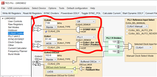
Master LMK input Frequency : 49.152 MHz

Master LMK output Frequency : 7.68 MHz

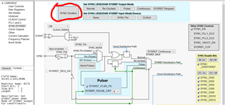
Which mode i need to prefer ? AS of now i am using Dual loop mode .so Please go through the tcs file and schematic and suggest me regarding the mode.

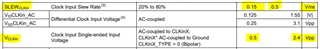
And in master we are getting CPout as 3.2V but as per data sheet (VCC/2). 

Note : Loop filter same as evm

But still we are having issue with PLL1 lock issue .

Master code.tcsSlave code.tcs

Slave is in Dual loop Nested mode  .

  • Hi Manasa,

    Your above description shows master LMK input frequency is 49.152MHz, whereas configuration file includes 61.44MHz at CLKin1 input. That could be reason of PLL1 lock issue. Also CLKin1_EN needs to be enable, which is giving the input at PLL1. 

    I am not sure, if you got the chance to go over the app note on Multi-clock synchronization, which gives the various options for multi device synchronization and their conditions for deterministic skew between clocks.

    Thanks!

    Regards,
    Ajeet Pal

  • Hi Ajeet,

    We changed the settings and we are operating master LMK in Dual loop mode and slave lmk in  Dual loop Zero delay nested mode

    Master input frequency :61.44MHz

    Vcxo Frequency : 122.88MHz

    Master output Frequency : 7.68 MHz

    This master output frequency we are feeding to slaves .

    Loop filter values same as EVM.And in master LMK input we are using Single ended clock .Please make sure our Tcs file is correct or not.

    4353.Master code.tcs8512.Slave code.tcs

  • Hi Manasa,

    Did you get the PLL1 locked after changing the settings?

    Master LMK dual loop mode can be used, if operating in jitter cleaner mode. Else, can use in single PLL (PLL2) with PFD frequency same as input frequency.

    As it's not operating in zero delay mode (ZDM), there may not be phase deterministic between the clock outputs. Hence, need to use SYNC divider for in-phase clocks out.

    So far settings look good and see the response on EVM.

    Regards,
    Ajeet Pal

  • Hi Ajeet ,

    Finally we are using master LMK in Clock distribution mode and slave LMK in Zero delay nested mode.

    Input Frequency of Master LMK : 245.76MHz

    Output Frequency Of Master LMK : 7.68 MHz

    Slave in Zero delay nested mode 

    Output of Slave : 245.76MHz

    But the issue is Lock indicating LED is blinking .We are getting some offset in Slave LMK frequency. I am attaching .tcs files of Master and Slave

    How to use sync and sysref pins in code for synchronization

    Clock distribution.tcs

    Slave_code for clock distribution.tcs

  • Hi Manasa,

    Master LMK config file looks good and I believe, you are getting the correct frequencies out from this.

    Regarding the Slave LMK, as you are feeding the single ended input to this and it needs to satisfy the input slew rate and input pk-pk voltage requirements at 7.68MHz CLKin inputs.

    You can verify the input signal specs and that could be the reason of PLL unlock/blinking.

    You can try with the LVCMOS single ended output from Master LMK, which will have higher pk-pk output and should work fine with it.

    Below is the graph for minimum input level requirement for single ended sine wave inputs over frequency and it needs higher input level for lower input frequency.

    Thanks!

    Regards,
    Ajeet Pal

  • Hi Ajeet,

    I am attaching block diagram of our architecture

    LMK Diagram.pdf

    Master LMK : clock distribution (245.76MHz or 122.88MHz)

    Master LMK out : 7.68MHz

    Slave LMk : Zero delay nested mode ( 245.76 output )

    All the slaves are locked.

    But when we are trying to give 61.44 or 30.72MHz frequencies to Master LMK in Clock distribution mode ,Slave(zero delay nested mode ) is not locking.

    i am attaching schematics of master and slave 

    2112.Master_LMK.pdf5736.Slave_LMK.pdf

    Loop filter same as EVM.

    Thanks & Regards,

    Manasa

  • Hi Manasa,

    It seems there were a mis-reporting, as Master LMK has single ended CLKin1 input which was thought of at Slave LMK input.

    I believe, Master LMK CLKin1 input has limited power issue. When the CLKin1 input frequency is higher, it is able to generate proper clock input to Slave LMK and getting PLL locked. Try to provide the more input power at Master LMK CLKin1 input as per above plot (previous reply) for single ended sinewave input power vs frequency for lower input frequency. It should able to generate clock out and get the Slave LMK locked.

    Thanks!

    Regards,
    Ajeet Pal

  • Hi Ajeeth,

    We tried increasing the amplitude for the master LMK but the result is same
  • Hi Manasa,

    Can you just try to check Master LMK test only by changing the input frequencies (245.76MHz, 122.88MHz, 61.44MHz and 30.72MHz) and see the output level at required frequency (7.68MHz)?

    As you mentioned above, for higher input frequency, secondary (slave) LMKs are locking and not with lower input frequencies. That seems, primary (master) LMK is not generating sufficient output level at lower input frequency that may be because of not sufficient input level.

    Regards,
    Ajeet Pal

  • Hi Ajeet,

    When we are using Master LMK in clock distribution mode and Slave in Zero delay nested mode.

    Master LMK frequency : 61.44MHz 

    Input Power : 13dBm

    Master output Frequency : 7.68MHz

    Slave output Frequency : 245.76MHz

    Amoung all 3 slaves

    only one slave was locked. Remaining slaves not locked

  • Hi Manasa,

    If you are running the same program in all 3 identical slave LMKs then, it suppose to lock all.

    Have you checked the Master LMK all 3 outputs, those are feeding to slave LMKs? Need to verify the master LMK 3 output frequencies and amplitude levels.

    Regards,
    Ajeet Pal