This thread has been locked.

If you have a related question, please click the "Ask a related question" button in the top right corner. The newly created question will be automatically linked to this question.

LMK04832: SYNC Pin Set and Hold time section 8.3.1.2 PLL2 R Divider

Part Number: LMK04832

We are noticing the highlighted statement below in the LMK04832 clock chip and are wondering what the setup and hold times are (specific values) that need to be met and which clock they are relative to in the context of the paragraph below? We didn’t see a timing table or diagram for the sync line.

Refn Section 8.3.1.2 of the datasheet....

  • Hi Steve,

    We're not exactly sure about hold time, but setup time is no greater than 150ps. In practice CLKin0 path is the only path which can practically achieve this setup time; there's ~3-5ns skew on the SYNC pin so treat the minimum setup time as 5ns through SYNC pin path and 150ps on CLKin0 path.

    I believe hold time should be very short, maybe also 150ps. This is all happening at the CLKin R divider, which is implemented in CML logic, so resets should happen very quickly; and unlike the other dividers the maximum frequency at the R divider (of both PLLs) is heavily limited, so the reset can typically happen very quickly. I'll double-check this before marking TI Thinks Resolved; if I hear differently, I'll post an update later today.

    Regards,

    Derek Payne

  • Steve,

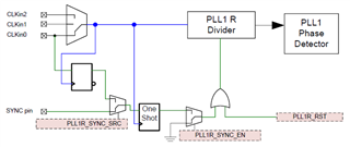
    I've confirmed that hold time for CLKin0 path should be very short. In practice I'll say 150ps, but I don't think anyone's going to be sending <300ps pulses to reset their R divider. A practical suggestion is at least 1/2 CLKin clock cycle. The same should be true for SYNC pin PLL1 R reset, though with ~3-5ns setup time due to propagation delay.

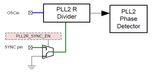
    PLL2 R divider reset can only go through the SYNC pin and is therefore dominated by ~3-5ns propagation delay on the SYNC pin. The minimum pulse width needs to be around 10ns for this signal to fully propagate through the digital logic. There isn't exactly a hold time limitation since the reset for the PLL2 R divider is asynchronous, as long as the pulse propagates through digital the whole PLL2 R divider will reset very rapidly (<150ps again). In theory you could generate a 10ns pulse with ~10ns setup time and barely any hold time and this would be sufficient. But it's sort of tricky to get the proper timing on the PLL2 reset due to the digital path on the SYNC pin having a long propagation delay, especially when PLL2 R divider is operating on a signal > 100MHz. So treat the minimum pulse width for PLL2 R divider as 10ns, and the setup time as a variable between ~3-5ns (assume 5ns worst case).

    Note that most of our customers use the PLL2 R divider as a divide-by-1, in which case there is no need for R divider reset.

    Here's some diagrams explaining the R divider SYNC paths for both PLL1 and PLL2 R dividers. I don't think these made it into the datasheet yet, but at some point they will be included. PLL1 R divider reset path has at least one retiming stage on hardware pins, with software reset being asynchronous; PLL2 path has no retimer and is fully asynchronous.

    Regards,

    Derek Payne