Part Number: LMK61E0M
Hi Team,
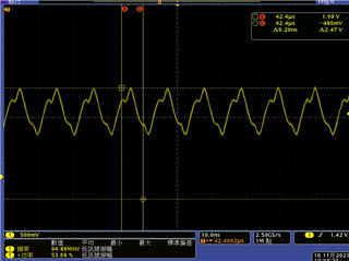
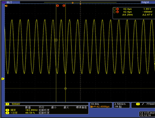
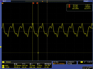
I used below setting to set LMK61E2M output frequency. (92Mhz and 184Mhz)
The 184MHz behavior looks good, but 92MHz is not ok. We tried 94MHz 90MHz and 91MHz, and the behavior were similar. Can you help me how to fix it?
R0	0x0010
R1	0x010B
R2	0x0200
R8	0x08B0
R9	0x0901
R16	0x1000
R17	0x1180
R20	0x1400
R21	0x1511
R22	0x1600
R23	0x1706
R24	0x1810
R25	0x1900
R26	0x1A33
R27	0x1B00
R28	0x1C00
R29	0x1D0D
R30	0x1E00
R31	0x1F00
R32	0x2019
R33	0x2103
R34	0x2224
R35	0x2327
R36	0x2418
R37	0x2502
R38	0x2602
R39	0x2707
R47	0x2F00
R48	0x3000
R49	0x3110
R50	0x3200
R51	0x3300
R52	0x3400
R53	0x3500
R56	0x3800
R72	0x4802
R0	0x0010
R1	0x010B
R2	0x0200
R8	0x08B0
R9	0x0901
R16	0x1000
R17	0x1180
R20	0x1400
R21	0x1511
R22	0x1600
R23	0x170D
R24	0x1810
R25	0x1900
R26	0x1A33
R27	0x1B00
R28	0x1C00
R29	0x1D0D
R30	0x1E00
R31	0x1F00
R32	0x2019
R33	0x2103
R34	0x2224
R35	0x2327
R36	0x2418
R37	0x2502
R38	0x2602
R39	0x2707
R47	0x2F00
R48	0x3000
R49	0x3110
R50	0x3200
R51	0x3300
R52	0x3400
R53	0x3500
R56	0x3800
R72	0x4802
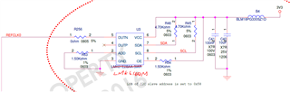
Schematic.
Roy