


Hi team,
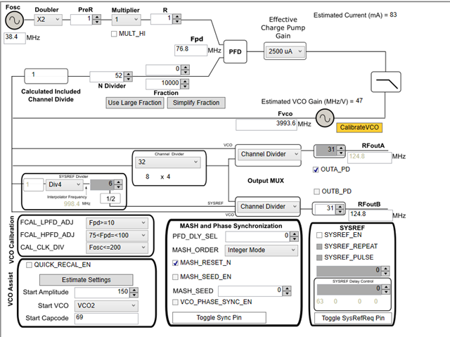
One of our customers encountered a problem when using LMX2572. There are many harmonic signals output. In their application, 38.4M single ended clock signal is used to input and output 124.8M clock. The configuration is generated by TICS Pro software, and then the configuration is imported into LMX2572. In addition to 124.8M clock, there are many other frequency signals, as shown in the following figure:

When VCO is configured as 3.9936g output, the spectrum is displayed as follows:

Register configuration:
ADDR DATA
R125 0x2288
R124 0x0000
R123 0x0000
R122 0x0000
R121 0x0000
R120 0x0000
R119 0x0000
R118 0x0000
R117 0x0000
R116 0x0000
R115 0x0000
R114 0x7802
R113 0x0000
R112 0x0000
R111 0x0000
R110 0x0000
R109 0x0000
R108 0x0000
R107 0x0000
R106 0x0007
R105 0x4440
R104 0x0000
R103 0x0000
R102 0x0000
R101 0x0000
R100 0x0000
R99 0x0000
R98 0x0000
R97 0x0000
R96 0x0000
R95 0x0000
R94 0x0000
R93 0x0000
R92 0x0000
R91 0x0000
R90 0x0000
R89 0x0000
R88 0x0000
R87 0x0000
R86 0x0000
R85 0x0000
R84 0x0000
R83 0x0000
R82 0x0000
R81 0x0000
R80 0x0000
R79 0x0000
R78 0x0001
R77 0x0000
R76 0x000C
R75 0x09C0
R74 0x0000
R73 0x003F
R72 0x0001
R71 0x0081
R70 0xC350
R69 0x0000
R68 0x03E8
R67 0x0000
R66 0x01F4
R65 0x0000
R64 0x1388
R63 0x0000
R62 0x00AF
R61 0x00A8
R60 0x03E8
R59 0x0001
R58 0x9001
R57 0x0020
R56 0x0000
R55 0x0000
R54 0x0000
R53 0x0000
R52 0x0421
R51 0x0080
R50 0x0080
R49 0x4180
R48 0x03E0
R47 0x0300
R46 0x07F1
R45 0xC63f
R44 0x1F63
R43 0x0000
R42 0x0000
R41 0x0000
R40 0x0000
R39 0x03E8
R38 0x0000
R37 0x0205
R36 0x0068
R35 0x0004
R34 0x0010
R33 0x1E01
R32 0x05BF
R31 0xC3E6
R30 0x18A6
R29 0x0000
R28 0x0488
R27 0x0002
R26 0x0808
R25 0x0624
R24 0x071A
R23 0x007C
R22 0x0001
R21 0x0409
R20 0x5048
R19 0x27B7
R18 0x0064
R17 0x0096
R16 0x0080
R15 0x060E
R14 0x1820
R13 0x4000
R12 0x5001
R11 0xB018
R10 0x10F8
R9 0x0004
R8 0x2000
R7 0x00B2
R6 0xC802
R5 0x30C8
R4 0x0A43
R3 0x0782
R2 0x0500
R1 0x0808
R0 0x2098
Best Regards,
Amy Luo

