This thread has been locked.

If you have a related question, please click the "Ask a related question" button in the top right corner. The newly created question will be automatically linked to this question.

CDCLVC1112: decoupling in magnetic field

Part Number: CDCLVC1112

Hi team, 

I received the following question, could you please take a look at it?

I am going to use a CDCLVC1112 unit to distribute a clock signal.

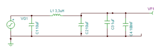
The datasheet recommends the use of a ferrite bead to decouple the power supply.

I am going to use this inside a static magnetic field, I have my concerns about if the ferrite bead will be affected (saturation) by the magnetic field.

 Do you think that I can use a air coil to decouple?

thanks, 
Jens 

  • Hi Jens,

    The CDCLVC1112 is an LVCMOS buffer, so the signal is composed of the fundamental and many higher-order harmonics in order to get a fast rise time and square edge. The intent of placing a ferrite bead in the power supply path is to put a high-impedance dissipative path (specifically with a high real resistance value at the target frequency) between the local bypass capacitors and the rest of the power supply circuitry, so high-frequency noise energy is dissipated as heat. As far as I know, an air-core inductor will not replicate the effect of increasing resistance at high frequency, so there will be no conversion of high-frequency energy to dissipated heat and the efficacy of the EMI reduction will be reduced. I also think you may have some difficulty sizing an air core inductor for the relevant frequency range, though I admit I have not investigated if there are devices available in a reasonable size and frequency range.

    That said, air core is better than nothing. Consider using a pi filter to improve the insertion loss and keep the higher-frequency harmonics local to the filter capacitors and ground plane between the filter and the CDCLVC1112. If you can keep the circuit overall close to the IC, there will be very little distance to act as an antenna for EMI to radiate away from the device, and most of the energy will remain local to the smallest filter loop inductances. Figure 13 suggests very large capacitance values in a ferrite-based pi filter, which should probably be accompanied by capacitors with higher frequency of minimum impedance if they are to be effective at standard LVCMOS frequency range without any other dissipative effects present.

    I'll also point out that EMI ferrites (anecdotally) tend to be usable even in fields up to 0.5T, though with diminished effectiveness. Above 0.5T static field there are not many materials which have headroom to saturation. So depending on the magnitude of the static magnetic field, there may still be options with ferrite beads worth investigating with a bead manufacturer (to get a better idea of material properties and saturation limits).

    Regards,

    Derek Payne

  • Hi Derek, 

    thank you for your detailed answer! 
    I received the following response: 

    "About the level of static magnetic field, I have not the exact values, but in the past we had some problems with magnetics fields in this zone with some ferrites, then, I prefer to use non magnetic components.
    I found a non magnetic coil of 3,3uH with 2,62x2,45mm package that can fit in the filter, LQW2UAS3R3J00L from Murata. And designed this filter:"


    Do you see any issues with that? 

    regards, 
    Jens 

  • Jens,

    The self-resonant frequency of this inductor appears to be around 90MHz; if this is close to the frequency of operation, then this component value is ideal for keeping a very high impedance. Otherwise you may want to select a different component with an SRF closer to the desired output frequency.

    Additionally, I didn't see any component model for this device on the manufacturer's website, but if you can locate one for slightly more accurate parasitic modeling this would be helpful. Often at high frequencies (>100MHz) the parasitic winding capacitance begins to act as a high-pass filter, so even though the fundamental and a few lower harmonics could be rejected, some higher harmonics could be high-passed back to the power supply.

    Make sure you keep the whole filter relatively close to the device. Ideally the filter should be on the same layer as the device, with a ground plane immediately beneath the buffer and the filter to confine the loop area of the return path through the filter capacitors.

    Regards,

    Derek Payne

  • Derek, 

    thanks for the excellent support!
    I received an additional question on this topic:
     

    "I found information about the static magnetic field, and the maximum will be around 100 mT. 

    reading your comment (above), the ferrite beads can be used even to 500 mT, then I will install a ferrite bead instead of the use of a magnet free coil.

    Can I use whatever ferrite bead, or I need to choose a special one to use it under magnetic field?"


    Regards, 
    Jens Tyslik

  • Jens,

    There's a good chance that a ferrous bead will still work without too much shift in impedance characteristics when subjected to only 100 mT. Ultimately this is also a question for the bead manufacturer, so I suggest reaching out to them as well for further confirmation - my anecdotal data is not worth nearly as much as a statement from the manufacturer, and there may be material characteristics for certain subsets of ferrite which differ from my anecdotal testing.

    Regards,

    Derek Payne