This thread has been locked.

If you have a related question, please click the "Ask a related question" button in the top right corner. The newly created question will be automatically linked to this question.

LMK00304: Is there Internal DC biasing? And clarifying terminations.

Part Number: LMK00304
Other Parts Discussed in Thread: LMK00306

I want to use the LMK00304 & LMK00306 buffers, but the datasheet doesn’t specifically indicate if the part has internal DC biasing. 
I am hoping you can provide clear guidance on connecting this part.

  1. Is this DC biased internally?
    1. If not, is there a recommended biasing?
  2. If AC coupled, LVDS input:
    1. Is a 100ohm between the differential nets all that is needed?
    2. Should that 100ohms be on the IC input side of the AC coupling?

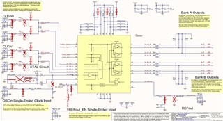
Also, the termination Figures 33 & 34 in the datasheet don’t match to what I would expect.  I downloaded the eval board schematic for this part, but it looks like it was reworked and doesn’t match the datasheet… actually matches what I would expect.

  • Hi Eric,

    To be clear, we're talking about the input of LMK00304? Figure 33/34 are included in your post, but those images depict LMK00304 as an LVDS output source, driving some generic receivers.

    In general, if our device recommends AC-coupling as an option on the input, it has internal DC biasing. That biasing is probably through relatively high DC resistance (e.g. 10kΩ or greater). In LMK00304 case, my expectation is that the bias point is set to around midrange on the supply voltage (1.65V on 3.3V supply or 1.25V on 2.5V supply) nominal, but it will easily be defeated by any output circuit with its own common mode biasing. The datasheet suggests the CLKinX DC-coupled VCM should be between 0.25V and VCC - 1.2V.

    For AC-coupled LVDS input, 100Ω just before the AC-coupling capacitors, all placed close to CLKinX on LMK00304, is all that is needed. Typically the 100Ω should be on the driver side of the caps, not the receiver side - if placed on the receiver side, it will bring the DC voltages of the pins very close together at steady state and overwhelm any built-in hysteresis at the CLKinX receiver circuit. For continuous clocks this doesn't really matter, since the DC levels at the receiver pins will always be distinct. For pulsed clocks (e.g. LVDS SYSREF repeater) or for clocks that must halt temporarily, receiver-side 100Ω isn't a good idea. The EVM as drawn is technically fine for continuous clocks, but not what I would recommend generally.

    Regards,

    Derek Payne