This thread has been locked.

If you have a related question, please click the "Ask a related question" button in the top right corner. The newly created question will be automatically linked to this question.

LMX2592: loop gain variation

Part Number: LMX2592


Hi team,

My customers are trying lower loop bandwidths with the LMX2592. The datasheet has the following plot showing a ~4kHz closed-loop bandwidth:


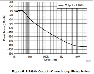
What loop filter component values were used for this test?

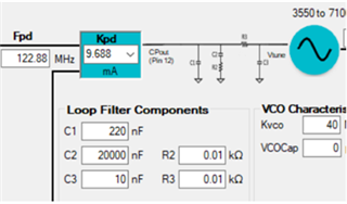
Customer is trying large capacitors in the loop filter and seeing large loop gain changes with small frequency adjustments.  PLLatimumSim does not show the gain variations they’re measuring.  Higher loop bandwidths (~ 100kHz) do not show this issue.

Thanks,

Connie

  • Hi Connie,

    What did you mean of large loop gain change? = Loop bandwidth?

    with a certain loop filter design, loop bandwidth will change with charge pump current or VCO gain (Kvco). Kvco will change with VCO frequency. 

    Do you have the PLL sim file and TICS Pro configuration?

  • Hi Noel,

    Yes, the customer meant loop BW change.  For some center frequencies, they are seeing very low loop bandwidth (~1kHz) when both sim and higher center frequencies (~10% higher) show expected performance.

  • Hi Connie,

    If you can get the PLL sim file and TICS Pro configuration, we can review to see if there is any way for improvement.

  • Hi Noel,

    Customer is still working thru the phase noise issue they see. They need help understanding the last three readback registers. Below is from a screenshot of TICSPro.  How do we interpret the HEX from R68, 69 and 70?


    R68 is VCO SEL; R 69 is VCO CNTL and R70 is VCO DACISET.  We see R68=0448 but R69=003C for 8512.5GHz and 00AC for 7862.5GHz.  R70 is 0188 for 8612.5 and 015F for 7862.5.

    Thanks,

    Connie

  • Hi Noel,

    Please ignore the last question. Customer was able to find the answer on another post.

    I have one more question - Can the TICSPro and USBAny tool readback PLL settings from the LMX2592 eval board?

    Thanks,
    Connie

  • Hi Connie,

    Yes, readback is possible. Set MUXOUT_SEL = 0x0, then from the Raw Registers page, we can read back a single register at a time or read back all registers at once.

  • Hi Noel,

    For some frequency settings, the PLL locks (LED on) but at ~ 30MHz offset (lower) from correct frequency. Customer only see this if the PFD Delay is set to 6 cycles.  The offset goes away if 4 cycles is used.  Below is the TICSPro settings they are using and that shows the frequency offset.


    Is this a known issue with this part?

    Thanks,

    Connie

  • Hi Connie,

    6-clk cycle is the datasheet suggested value, this register could affect phase noise and pll lock if it is not set properly.

    With 6-clk cycle and 4-clk cycle, how do the output signal look like? I expect there should be some difference.

    If 4-clk cycle works better, I have no objection to use this value.

    BTW, FCAL_HPFD_ADJ was not set properly, it should be equal to 0x1.

  • Hi Noel,

    The plot below is for the LMX2592 on customer's PCB and controlled with their software.  Attached are the readback files for the device on their board (note it shows R69 and R70).  These register setting agree with the eval board’s settings.  The loop gain at 30kHz offset shows nearly 10dB variation with only a 10% change in tune frequency. Using the same loop filter components on the eval board, they do not see this big gain change.  Any suggestions about what might be causing this?


    Low frequency, below does not show this ‘hump’ of phase noise at 30kHz:


    Below shows loop gain change at 30kHz offset with tune frequency change (black trace is 8512.5MHz, Blue 7962.5MHz):

    Programming seems correct, but the reduced attenuation (higher loop gain) at the high frequency is causing the higher phase noise at 30kHz offset.  Note that in between the high and low frequencies, we see a gradual change in 30kHz offset phase noise increasing to 10dB at the high end.  The only thing changed was the tune frequency*.

    *the lowest frequency does change the phase detector frequency to half that of all the others to comply with the minimum divider setting.  Loop filter:


    Nothing in their system is changing when the PLL is tuned to the higher frequency other than the PLL.  Any help to pin down this issue would be appreciated.


    R00 : 0x2218
    R01 : 0x0808
    R02 : 0x0500
    R03 : 0x1902
    R04 : 0x1943
    R05 : 0x00C8
    R06 : 0xC802
    R07 : 0x28B2
    R08 : 0x1084
    R09 : 0x0302
    R10 : 0x10D8
    R11 : 0x0018
    R12 : 0x7001
    R13 : 0x4000
    R14 : 0x0FFC
    R15 : 0x0025
    R16 : 0x0037
    R17 : 0xE114
    R18 : 0x03C0
    R19 : 0x0965
    R20 : 0x012C
    R21 : 0x0064
    R22 : 0x2300
    R23 : 0x8842
    R24 : 0x0509
    R25 : 0x0000
    R26 : 0x027C
    R27 : 0x071A
    R28 : 0x2924
    R29 : 0x0084
    R30 : 0x0035
    R31 : 0x0001
    R32 : 0x210A
    R33 : 0x2A0A
    R34 : 0xC3CA
    R35 : 0x119F
    R36 : 0x0048
    R37 : 0x5000
    R38 : 0x0022
    R39 : 0x8104
    R40 : 0x000F
    R41 : 0x4240
    R42 : 0x0000
    R43 : 0x0000
    R44 : 0x0004
    R45 : 0xDD05
    R46 : 0x0F22
    R47 : 0x08CF
    R48 : 0x03FD
    R49 : 0x0300
    R50 : 0x0300
    R51 : 0x4180
    R52 : 0x0000
    R53 : 0x0080
    R54 : 0x0820
    R55 : 0x0000
    R56 : 0x0001
    R57 : 0x0000
    R58 : 0x0000
    R59 : 0x0000
    R60 : 0x0000
    R61 : 0x0001
    R62 : 0x0000
    R63 : 0x0094
    R64 : 0x0077
    R65 : 0x2801
    R66 : 0x0002
    R67 : 0x9D7D
    R68 : 0x0448
    R69 : 0x003C
    R70 : 0x0188
    ok
    R00 : 0x2218
    R01 : 0x0808
    R02 : 0x0500
    R03 : 0x1902
    R04 : 0x1943
    R05 : 0x00C8
    R06 : 0xC802
    R07 : 0x28B2
    R08 : 0x1084
    R09 : 0x0302
    R10 : 0x10D8
    R11 : 0x0028
    R12 : 0x7001
    R13 : 0x4000
    R14 : 0x0FFC
    R15 : 0x0025
    R16 : 0x0037
    R17 : 0xE114
    R18 : 0x03C0
    R19 : 0x0965
    R20 : 0x012C
    R21 : 0x0064
    R22 : 0x2300
    R23 : 0x8842
    R24 : 0x0509
    R25 : 0x0000
    R26 : 0x027C
    R27 : 0x071A
    R28 : 0x2924
    R29 : 0x0084
    R30 : 0x0035
    R31 : 0x0001
    R32 : 0x210A
    R33 : 0x2A0A
    R34 : 0xC3CA
    R35 : 0x119F
    R36 : 0x0048
    R37 : 0x5000
    R38 : 0x003E
    R39 : 0x8104
    R40 : 0x000F
    R41 : 0x4240
    R42 : 0x0000
    R43 : 0x0000
    R44 : 0x000F
    R45 : 0x2552
    R46 : 0x0F22
    R47 : 0x08CF
    R48 : 0x03FD
    R49 : 0x0300
    R50 : 0x0300
    R51 : 0x4180
    R52 : 0x0000
    R53 : 0x0080
    R54 : 0x0820
    R55 : 0x0000
    R56 : 0x0001
    R57 : 0x0000
    R58 : 0x0000
    R59 : 0x0000
    R60 : 0x0000
    R61 : 0x0001
    R62 : 0x0000
    R63 : 0x0094
    R64 : 0x0077
    R65 : 0x2801
    R66 : 0x0002
    R67 : 0x9D7D
    R68 : 0x0448
    R69 : 0x00AC
    R70 : 0x015F

  • Hi Connie,

    FCAL_HPFD_ADJ is not right in 8512.5MHz setting, this might lead to wrong calibration.

    TICS Pro and PLL Sim assume VCO1 and VCO2 for 7862.5MHz and 8512.5MHz respectively. Their Kvco are similar, so when fpd is cut into half, loop bandwidth shall be reduced by a half. From PLL Sim, the loop bandwidth at 7862.5Mhz and 8512.5MHz are 8.04kHz and 13.63kHz respectively.

    However, from register readback, VCO2 was selected (from calibration) at both frequencies.

    As a result, the loop bandwidth at 7862.5MHz becomes 5.8kHz. Since the phase margin at both frequencies are greater than 75 degrees, their phase noise plots are actually similar, we are not able to tell the loop bandwidth difference from the plots.

    In summary, we should see similar phase noise plots at these frequencies despite their fpd and loop bandwidth are different. 

    Regarding the "hump", this could be due to the reference clock. In above simulations, the phase noise of the reference clock was not taken into account. If the hump was due to the reference clock, a smaller loop bandwidth can reduce the hump more.

    Was the customer using different reference clock in their board and in EVM?