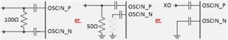
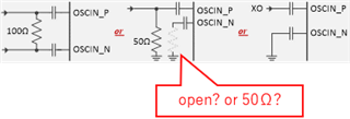
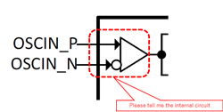
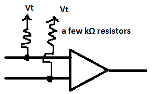
Please tell me the internal circuit (internal connection) of OSCIN_P(Pin.8) and OSCIN_N(Pin.9).

-
Ask a related question
What is a related question?A related question is a question created from another question. When the related question is created, it will be automatically linked to the original question.