This thread has been locked.

If you have a related question, please click the "Ask a related question" button in the top right corner. The newly created question will be automatically linked to this question.

LMK05318: LMK05318 EVM

Part Number: LMK05318

Hi all

Would you mind if we ask LMK05318?
Could you refer to the .tcs file and scope figures?

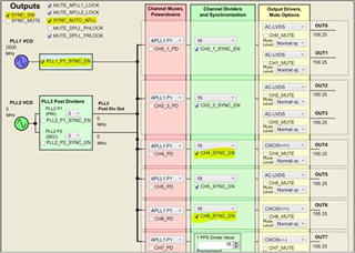
■1__EVM-default__Select-PLL2__211220.tcs■
OUTPUT0~7 156.25MHz with PLL2 VCO, LMK05318's EVM
→ We got scope_9.bmp, it seems that input is synchronized with output.(OK)
    (scope_9.bmp is overlapped display with several wave forms.)

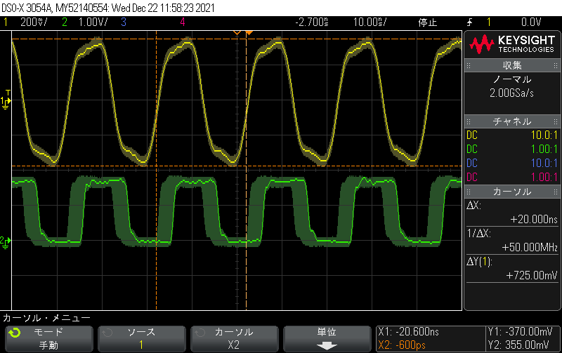
■2__EVM-default__OUT-Freq25M__211220.tcs■
OUTPUT0~7 25MHz with PLL1 VCO, LMK05318's EVM
→ We got scope_13.bmp, it seems that input is synchronized with output.(OK)

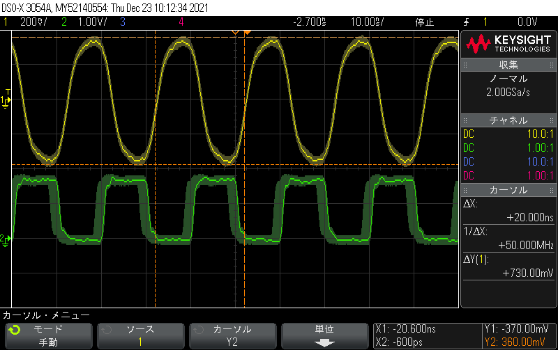
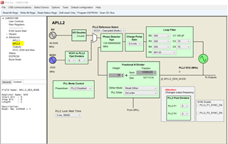
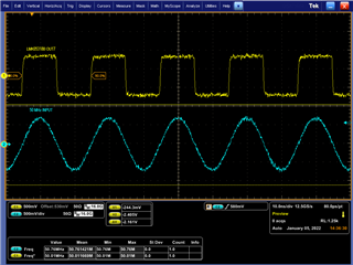
■3__EVM-default__OUT-Freq25M__Select-PLL2__211220.tcs■
OUTPUT0~7 25MHz with PLL2 VCO, LMK05318's EVM
→ We got scope_14.bmp, it seems that input is not synchronized with output.(NG)
So, we don't understand why input is not synchronized with output and it seems that jitter increases.
If you have some advice, could you let us know?
We assume that it is possible to confirm these using EVM.

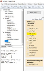
*On the TICSPRO operation, the customer executed Calculate frequency -> Run scriprt in any case.

20211221_Scope9, Scope13, Scope14.pdf

1__EVM-default__Select-PLL2__211220.tcs

2__EVM-default__OUT-Freq25M__211220.tcs

3__EVM-default__OUT-Freq25M__Select-PLL2__211220.tcs


Kind regards,

Hirotaka Matsumoto

  • Hello Hirotaka,

    1. To synchronize the outputs, the following controls need to be set as shown in the image below:
      1. CHx_SYNC_EN needs to be set high.
      2. SYNC_MUTE should be disabled so that the output drivers are not muted during a SYNC event.
      3. SYNC_AUTO_APLL needs to be set high.
      4. PLL1_P1_SYNC_EN needs to be set high.
      5. Once the sync controls have been set, toggle (turn on and off) the SYNC_SW control to assert the output synchronization.

    Regards,

    Kia Rahbar

    1. Kla san


      Thank you so much for your cooperation!

      1. To synchronize the outputs, the following controls need to be set as shown in the image below:
        1. CHx_SYNC_EN needs to be set high.
        2. SYNC_MUTE should be disabled so that the output drivers are not muted during a SYNC event.
        3. SYNC_AUTO_APLL needs to be set high.
        4. PLL1_P1_SYNC_EN needs to be set high.
        5. Once the sync controls have been set, toggle (turn on and off) the SYNC_SW control to assert the output synchronization.


      -> The customer confirmed with your mention with following .tcs file, however the result was the same as following wave form.

      4-3__EVM-default__OUT-Freq50M__Select-PLL2__211221.tcs


      CH1=PRE-Reference
      CH2=OUTPUT7

      The customer confirmed these with EVM, so could you confirm it using LMK05318's EVM?


      Kind regards,

      Hirotaka Matsumoto


    2. Hello Hirotaka,

      Apologies, there is one more bit that needs to be set. Please perform the following sequence:

      1. CHx_SYNC_EN needs to be set high.
      2. SYNC_MUTE should be disabled so that the output drivers are not muted during a SYNC event.
      3. SYNC_AUTO_APLL needs to be set high.
      4. PLL1_P1_SYNC_EN needs to be set high.
      5. DPLL_ZDM_SYNC_EN needs to be set high to synchronize the input and output.
      6. Once the sync controls have been set, toggle (turn on and off) the SYNC_SW control to assert the output synchronization.

      Please note OUT7 is the only output with ZDM capabilities.

      Regards,

      Kia Rahabr

    3. Kia san

      Thank you so much for your cooperation always.

      1. CHx_SYNC_EN needs to be set high.
      2. SYNC_MUTE should be disabled so that the output drivers are not muted during a SYNC event.
      3. SYNC_AUTO_APLL needs to be set high.
      4. PLL1_P1_SYNC_EN needs to be set high.
      5. DPLL_ZDM_SYNC_EN needs to be set high to synchronize the input and output.
      6. Once the sync controls have been set, toggle (turn on and off) the SYNC_SW control to assert the output synchronization.

      -> The customer confirmed with your mention with following .tcs file, however the result was the same as following wave form.

      4-4__EVM-default__OUT-Freq50M__Select-PLL2__211221.tcs


      The customer confirmed these with EVM, so could you confirm it using LMK05318's EVM?
      Then, we think both waveforms seem that are synchronized.
      We seem that OUTPUT7 has jitter. It is cause of jitter. 


      Furthermore, should we "PLL2_P1_SYNC_EN  or PLL2_P2_SYNC_EN" set? Because we mention PLL2.  

      Kind regards,

      Hirotaka Matsumoto

    4. Kia san

      If you have some update, could you let us know?

      And then, could you let us know how to operate APLL2's calibration?
      We think we should operate each VCO's calibration.
      Is it correct?

      Kind regards,

      Hirotaka Matsumoto

    5. Hello Hirotaka,

      The 50 MHz output clocks can be outputted from APLL1. Is there a reason you need to use APLL2? APLL1 will result in better phase noise performance as well.

      I have created an updated configuration for the 50 MHz outputs using APLL1. I would recommended using this configuration.

      4-4__EVM-default__OUT-Freq50M__Select-PLL1__211228.tcs

      Regards,

      Kia Rahbar

    6. Kia san

      Thank you for your update.

      The 50 MHz output clocks can be outputted from APLL1. Is there a reason you need to use APLL2? 
      ->The customer set the 50MHz output as the test. They will use 148.5MHz output eventually.
          APLL1 can not generate  148.5MHz output.

      We would like to know followings;
      -Why does the jitter increase in case of APLL2 cascade connections?
      -How to operate calibration of APLL2


      Kind regards,

      Hirotaka Matsumoto

    7. Hello Hirotaka,

      APLL2 clock outputs have a higher jitter because it does not have the BAW VCO technology that APLL1 has. APLL1's VCO frequency is locked to one specific frequency (2.5 GHz), so there will be less frequency deviation and jitter on the output clocks.

      APLL2 calibration can be completed on the APLL2 page on TICS Pro.

      Regards,

      Kia Rahbar

    8. Kia san

      Thank you for your update.

      APLL2 clock outputs have a higher jitter because it does not have the BAW VCO technology that APLL1 has.
      APLL1's VCO frequency is locked to one specific frequency (2.5 GHz), so there will be less frequency deviation and jitter on the output clocks.
      ->Of course, we know APLL2 clock outputs have a higher jitter than APLL1's jitter because APLL2 is LC-VCO.
          As what we want to know, the following waveform is bigger jitter which we assume.
          Is it normal operation for you also?(Within your assumption?)


      APLL2 calibration can be completed on the APLL2 page on TICS Pro.
      ->We would like to know detail.
         There is the description on the datasheet "A VCO calibration can be triggered manually for a single APLL by toggling a PLL power-down cycle (PLLx_PDN bit = 1 → 0) through host programming.This may be needed after the APLL N divider value (VCO frequency) is changed dynamically through programming."
         By toggling a PLL power-down cycle (PLLx_PDN bit = 1 → 0), does calibration operate?


      Kind regards,

      Hirotaka Matsumoto

    9. Hello Hirotaka,

      Of course, we know APLL2 clock outputs have a higher jitter than APLL1's jitter because APLL2 is LC-VCO.
      As what we want to know, the following waveform is bigger jitter which we assume. Is it normal operation for you also?(Within your assumption?)

      -> As long as APLL2 is locking properly and providing the correct output frequency (which it appears to be doing in your scope image), then I do not see an issue. Here is where you can verify PLL2 is locking properly:

      By toggling a PLL power-down cycle (PLLx_PDN bit = 1 → 0), does calibration operate?

      -> Yes, that is correct. Toggling PLL2_PDN bit will calibrate APLL2. Here is the register for PLL2_PDN:

      Regards,

      Kia Rahbar

    10. Kia san

      Thank you for your reply.

      As our request, we don't have LMK05318EVM, so could you test using LMK05318EVM with customer's .tcs file?
      If it doesn't occur under your test, we will inform our customer that the customer setting is wrong.

      Kind regards,

      Hirotaka Matsumoto

    11. Hello Hirotaka,

      Today I tested the 4-4__EVM-default__OUT-Freq50M__Select-PLL2__211221.tcs file on one of our EVMs and found that the jitter was correct and the input to output clock signals were synchronized.

      Here are the phase noise plot and scope capture for your reference:

      Regards,

      Kia Rahbar

    12. Kia san

      Thank you so much for your great cooperation always!
      OK, we got it.

      Just in case, we would like to confirm one point.

      Our customer configures TICSPRO with LMK05318(without -B), is there no difference the funcition?
      Abour EVM, is there only LMK05318BEVM?


      Kind regards,

      Hirotaka Matsumoto

    13. Hello Hirotaka,

      There is no difference whether the LMK05318 or LMK05318B GUI is used. The registers will be the same for both devices.

      There are EVMs for both the LMK05318B and LMK05318. The EVMs can be ordered at the following links:

      https://www.ti.com/store/ti/en/p/product/?p=LMK05318EVM

      https://www.ti.com/store/ti/en/p/product/?p=LMK05318BEVM

      Regards,

      Kia Rahbar

    14. Kia san

      Thank you for your update.
      OK, we got it.

      <Request1>
      Just in case, please let us know the wave form you captured.
      Is it possbile to capture using persistence mode(overwriting, during 30sec)? 
      Because our customer captured with persistence mode.

      <Request2>
      And, is it possible to let us know your measurement conditions?(oscilloscope and prove)
      If it contains confidential contents, could you send these using private message on E2E?
      Because, we doubt that our customer's measurement conditions are enought or not. 

      <Question1>
      The customer uses LMK05318EVM(without -B).
      We think there is no difference about function between -B and null.
      We assume that there are difference jumper setting and power supply. 
      Is it correct?


      We appreciate your help always!

      Kind regards,

      Hirotaka Matsumoto

    15. Hello Hirotaka,

      The capture was made with persistence enabled and the measurements were made on a LMK05318EVM board connected to a Tektronix oscilloscope.

      Yes, the LMK05318EVM has different jumper settings than the LMK05318BEVM. Here is the LMK05318EVM user guide: https://www.ti.com/lit/ug/snau236a/snau236a.pdf?ts=1641496965939&ref_url=https%253A%252F%252Fwww.google.com%252F

      Please reference this for the appropriate jumper and power supply settings.

      Regards,

      Kia Rahbar

    16. Kia san

      Thank you for your reply!

      The capture was made with persistence enabled and the measurements were made on a LMK05318EVM board connected to a Tektronix oscilloscope.
      ->Just in case, is "LMK05318EVM" or LMK05318BEVM?
         Then, your jumer settings are default setting, right?

      And is it possible to let us know oscilloscope and prove?

      Kind regards,

      Hirotaka Matsumoto


    17. Kia san

      We found why the customer's setting increases jitter.
      PFD frequnecy = 138.88888888888MHz
      VCO frequnecy = 5500MHz
      In this case, fractional N divider should be 39.6.
      Using runscript, fractional N divider was 39.5999999642372131
      So, we modified it, and the wave form inproved.


      However, we have another problem.

      The customer would like to realize following using LMK05318; 
      REF 50MHz -> OUTPUT 148.5MHz with VCO1' cascade mode. 

      REF 50MHz -> APLL1 BAW2500MHz -> APLL2 LCVCO 5643MHz -> 148.5MHz

      In this case, BAW frequency is 2.5GHz fixed.
      And LMK05318 can't configure APLL2's denominator.

      Is it possible to configure?
      We assume that APLL2's fractional N divider will be incorrect value. As the result, incorrect value increases jitter also.
      In this case, does it need to use LMK05318B?

      Kind regards,

      Hirotaka Matsumoto

    18. Hello Hirotaka,

      Yes, the LMK05318B will be required. The LMK05318B allows for a programmable APLL2 denominator.

      The LMK05318 and LMK05318B are p2p replacements. For future reference, we recommend using the LMK05318B only.

      Regards,

      Kia Rahbar

    19. Kia san

      Thank you for your reply.

      The LMK05318 and LMK05318B are p2p replacements. 
      ->Our customer would like to replace LMK05318B on LMK05318EVM(-null EVM).
          Is it possible to set on LMK05318B to LMK05318EVM(-null EVM)?
          If you have some advice, could you let us know?

      Kind regards,

      Hirotaka Matsumoto

    20. Hello Hirotaka,

      Yes, it is possible to place the LMK05318B on the LMK05318EVM. You will have to de-solder the LMK05318 currently on the board and then solder on the LMK05318B.

      Regards,

      Kia Rahbar