This thread has been locked.

If you have a related question, please click the "Ask a related question" button in the top right corner. The newly created question will be automatically linked to this question.

LMK04828: PLL1 is not locking

Part Number: LMK04828


Hi everyone,

I am using LMK04828B with following Connections for the output frequency of 200MHz.

CLKin0 input frequency – 25MHz from TCXO
CLKin1 input frequency – 25 MHz from signal generator
OSCin frequency – 100MHz from VCXO

I am using dual PLL mode with CLKin0 input.

I observed PLL1 not locking problem in one of the production unit.

I am using following register configuration. (File is attached here)

I have done following test for PLL1 loss of locking issue.

1. I changed PLL2_N_CAL value (0x0165 register) = PLL2_N. But Still PLL1 was not locked.
2. I checked with CLKin1 input from Signal Generator. PLL1 was locked. Hence I suspected CLKin 0 25MHz from TCXO. But I probed both working and not working module CLKin0 inputs. There is no difference between working and not working board.
3. I read all the register values what are written through SPI at PLL1 not locking condition. (attached here)
4. As per the read back status of following registers, PLL1 is entered into Holdover mode. Please refer the following Table and clarify my queries

Address Readback Data from PLL1 & PLL2 locking Module Readback Data from PLL1 (not locking) & PLL2 locking Module Observations and Queries
0x182 6 0 PLL1 Lock Detect is not high. In both condition I have not give input at CLKin1 Pin. But CLKin1 LOS is active in working module alone. Why?
0x184 48 88
0x185 FF 0 DAC value is changing to 511 instead of 512. Will it impact PLL1 Locking?
0x188 0 10 PLL is entered into Holdover state Why?

Please provide your support.

Thanks,
Vignesh6253.Attachments.zip

  • Hi Vignesh,

    • Can you share the PLL1 loop filter and the VCXO gain in ppm/V or kHz/V? The loop may not be stable since the VCXO and the phase detector frequency were modified compared to EVM defaults
    • What is the input amplitude of the 25MHz from TCXO? From signal generator? Is it possible that the input amplitude isn't sufficient to achieve clean high/low threshold values in MOS mode?
    • Have you AC-coupled the input in MOS mode? This could change the distance for the signal from the high/low thresholds. MOS mode supports DC-coupling from 3.3V LVCMOS.
    • I see that you are using pin select mode for CLKin_SEL_MODE - are you sure the input to the CLKin_SEL0 and CLKin_SEL1 pins is correct for both systems?

    For your specific differences breakdown:

    • I would not pay attention to CLKin1 LOS status, since LOS is not enabled. This field may not be correct in either case without enabling LOS.
    • DAC value changing from 511 to 512 or vice versa is within expectations - both values are close to midrange voltage for the charge pump output in holdover mode.
    • Since you're in pin select mode, I suspect you're in holdover because the pin selection is forcing you into holdover... but other questions above could help point to other issues.

    Regards,

    Derek Payne

  •   Dear sir,

    Kindly find our reply for your queries,

    1)Can you share the PLL1 loop filter and the VCXO gain in ppm/V or kHz/V? The loop may not be stable since the VCXO and the phase detector frequency were modified compared to EVM defaults

              Reply: PLL1 loop filter and the VCXO configuration was same as the EVM defaults.
     
        2)What is the input amplitude of the 25MHz from TCXO? From signal generator? Is it possible that the input amplitude isn't sufficient to achieve clean high/low threshold values in MOS mode?
      
          Reply:

          a)For use of internal clock:25MHz input  with amplitude of 2.41V

          b)For use of external clock:Applied input as 25MHz with -5dBm to +5dBm range

        3)Have you AC-coupled the input in MOS mode? This could change the distance for the signal from the high/low thresholds. MOS mode supports DC-coupling from 3.3V LVCMOS.

          Reply: We are using CLKin pins are being driven with a single-ended LVCMOS/LVTTL source and its supports the MOS mode 3.3V LVCMOS only
      
        4)I see that you are using pin select mode for CLKin_SEL_MODE - are you sure the input to the CLKin_SEL0 and CLKin_SEL1 pins is correct for both systems?

           Reply: Internal clock is applied to the CLKin0 and the pin select mode latching as 00 for CLKin_SEL0 and CLKin_SEL1.It has same for both the working & not-working system.
                 

    Note:PLL 1 is not locked while giving the clock for the 1st time through signal generator.After loading the LMK PLL configuration file,Once disable and enable the external clock and the same PLL 1 was locked successfully.

  • Vignesh,

    Regarding loop filter: I am confused how the EVM defaults could be used when you claim a 100MHz VCXO - the EVM is supplied with a 122.88MHz VCXO by default. If you used a Crystek CVHD-950 VCXO with 100MHz, I can understand the claim. But a different VCXO could have a different pull range, or different divider settings could result in a different phase detector frequency, which could affect the loop stability. Did you change the VCXO? Did you change the PFD frequency?

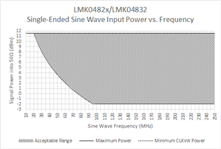
    The clock amplitudes seem okay, as long as it gets above 2V and below 0.4V it should trigger. The external 25MHz clock amplitude should probably be higher if it is a sinewave, at least +10dBm, to satisfy the minimum slew rate requirement as well (0.15V/ns implies about 9.7dBm required amplitude at 25MHz to achieve the necessary slew rate) - see the graph below.

    If you toggle the CLKin_SEL pins so that a different input is selected, and then return to the correct input, do you see lock? This could suggest an issue with the clock switching state machine.

    If you compare the VCXO phase to the TCXO phase, do you see that they are approximately stable? The lock detect may not be succeeding if the ppm offset between the VCXO and the TCXO is naturally very close, but the VCXO and TCXO start up at enough of a phase offset that the lock detect is not registering a true phase lock. You can try tri-stating the PLL1 charge pump to simulate a momentary glitch on the VCXO control pin, which will force the ppm error on the VCXO to change relative to the TCXO ppm error - if tri-stating the PLL1 charge pump a few times doesn't result in a stable lock, or if the TCXO and VCXO phase are not stable during the unlock condition, there is a different problem at work.

    Regards,

    Derek Payne