This thread has been locked.

If you have a related question, please click the "Ask a related question" button in the top right corner. The newly created question will be automatically linked to this question.

LMK05318B: TICSPRO error message

Part Number: LMK05318B


Hi all

Would you mind if we ask LMK05318B?

We attach the .tcs file

20220113_REF-54M053998__OUT7-54M053998__220113.tcs

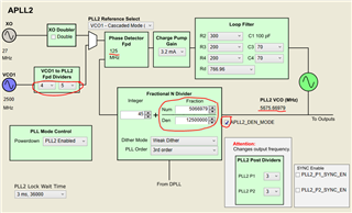
In case of operating Run Script on Set DPLL, it shows error message.

Warning: The input contains a value greater than the maximum contiguous flint.
(In our OS, it is showed by japanese, so the spells might be not  correct.)

Could you let us know how to modify it?

Kind regards,

Hirotaka Matsumoto

  • Hello Matsumoto-san,

    Basically this means that the floats being used in the DPLL calculation exceed the maximum contiguous range of a floating point number. Because the numerator and denominator are eventually coerced to fit within the 2^40 bit range of the DPLL numerator/denominator registers, any issues with non-continuous floats are actually avoided. I've checked the outputs with an internal variable modified to prevent this issue, and the register output files are identical.

    If you still want to eliminate the issue altogether:

    • Navigate to C:\ProgramData\Texas Instruments\TICS Pro\Configurations\Devices\Network Synchronizer Clock (Digital PLLs)\LMK05318B
    • Open the file "LMK05318B_wizard.py"
    • Go to line 1660 and replace the line, rather than "1e9":
      • self.dpll_ref_common_div = "1"

    Regards,

    Derek Payne

  • Derek san


    Thank you so much for your reply.
    OK, we got it.

    We have additional question.
    On 20220113_REF-54M053998__OUT7-54M053998__220113.tcs files,
    OUTPUT7 frequency shows 54.054MHz.


    On the calculation using VCO and divider, 
    -VCO : 5675.6698MHz 
    -PLL2 Post Dividers : 5 
    -OUTPUT7 divider :21
    5675.6698MHz ÷ 5 ÷ 21 = 54.0539980952381MHz
    However, TICSPRO shows 54.054MHz.

    Will actual output frequency be 54.0539980952381MHz?

    Kind regards,

    Hirotaka Matsumoto

  • Matsumoto-san,

    Yes, the output will have a slight PPB error with the default denominator on PLL2. One way to correct this is with manual DCO, but this requires a loop to correct the error over time. If we want to ensure that there is zero PPB error by design, we can modify the PLL2 configuration manually using the APLL2_DEN_MODE bit, and change the cascading reference dividers:

    54.053998MHz * 5 * 21 = 5675.66979MHz

    2500MHz / 20 = 125MHz

    5675.66979MHz / 125MHz = 45 + 5_066_979 / 12_500_000 (underscores for readability)

    We would make the following changes on the Advanced -> APLL2 page:

    • PLL2_RDIV_PRE = divide-by-4 (up from 3)
    • PLL2_RDIV_SEC = divide-by-5 (down from divide-by-6)
    • APLL2_DEN_MODE = 1
    • PLL2_NUM = 5066797
    • PLL2_DEN = 12500000

    Regards,

    Derek Payne