This thread has been locked.

If you have a related question, please click the "Ask a related question" button in the top right corner. The newly created question will be automatically linked to this question.

LMK1D1216EVM: Single-Ended Input Configuration

Part Number: LMK1D1216EVM

Hello,

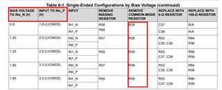
Table 6.1 of the LMK1D1216EVM user guide details the rework necessary to modify the EVM to accept a single-ended input clock. However, instead of applying an appropriate Vth level at the INx_N leg of the pair, the rework seems to be targeting the INx_P leg instead.

There are also reference designators called out (Remove Common-Mode Resistor column) that don't seem to be related to the input termination for these clock lines?

An uprev to address this table might help future readers.

Thank You,

David

  • David,

    There's a few things here that don't line up with the schematic. This table is sort of a mess. I'll make a note to update it in our literature backlog.

    The general strategy for either pin is to set the common mode bias using the pull-up to VCC and the R52/R53 components to GND as a divider, along with one of R56/R57/R58/R59 as a 0Ω for the common-mode pin. Importantly, either R62 or R63 should be removed, so that the common mode setpoint established by VAC_REF0/1 do not conflict with the resistor divider biasing. I don't think the table conveys this well, and we would probably benefit from a schematic image showing the outcome of the changes in at least one case.

    Regards,

    Derek Payne