Part Number: LMX2592
Hello,
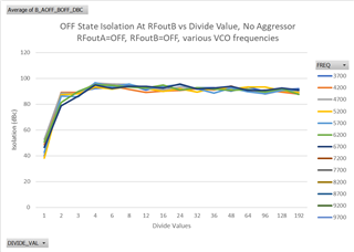
How much is the isolation between Cha-A and Ch-B in LMX2592?
Regards,
Naveen.A
Original question:

Part Number: LMX2592
Hello,
How much is the isolation between Cha-A and Ch-B in LMX2592?
Regards,
Naveen.A