This thread has been locked.

If you have a related question, please click the "Ask a related question" button in the top right corner. The newly created question will be automatically linked to this question.

CDCE72010: Write to CDCE72010 EEPROM

Part Number: CDCE72010

Hi, 

Can the EVM board be use with only 5V from the USB port supply while maintaining the state of the EEPROM with power off and on? 

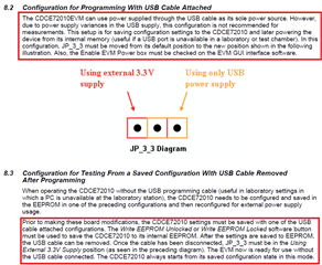
Setup condition: After the EEPROM is being programmed. and JP_3_3 is retain at USB power supply. Off the USB 5V supply and power up again the output clock is not working. 

Thanks.

  • Hi,

    CDCE72010EVM can powered up with 5V USB port also and can use the EEPROM write. Later if you need, can remove the USB and powered up with external supply and it would work.

    https://www.ti.com/lit/ug/slau250/slau250.pdf

    Thanks!

    Regards,

    Ajeet Pal

  • I mean, after the EVM is programmed. The EVM is later to be supply by only the 5V USB as sole supply without other external supply. 

    How can we do that to have EVM working with USB 5V supply only? 

  • Hi,

    As mentioned in section 8.2 in above image, USB 5V supply is solely used for programming purpose and not recommended for measurement as there can be power supply variance in the USB supply. 

    But if you still wants to verify with USB 5V supply, the connections JP_3_3 should be retain as default for USB supply and it should work.

    If after programming, you are not getting the clock out I would be suspecting the program sequence you may have followed.

    1. Have you tried with factory programmed device performance with USB supply? If it works, you need to look on your programming sequence.

    2. Have you tried after program with external supply 3.3V? If it works, then check the 3.3V LDO output by USB 5V supply.

    Thanks!

    Regards,

    Ajeet Pal

  • Top op, 

    Step of programming and test usage:

    1. connect usb to EVM board from a PC. JP_3_3 is selected at USB power supply
    2. Open CDCE72010 Control GUI then load .ini file. (EVM board is working as intended with output of 491.52MHz)
    3. Write EEPROM Locked with Enable EVM Power.
    4. Usage condition, remove usb supply , connect 3.3v supply and change JP_3_3 to 3.3v. -> output of the clock is not at 491.52MHz. Value is shifted  a little and not exact the same value!!.
    5. scenario 2 , to only use 5v supply, from usb no clock output. 

    add on 5v supply from USB and the clock out is giving out exact at 491.52MHz. if without the 5v supply , the and amplitude is fine but freq is shifted. 

    Is it the case the board require both supply to work at stable condition? Cause per understanding is that, the board can use only with 3.3V supply only. Thanks.

  • Hi,

    Primary Input and secondary inputs would need an biasing, it can be done through internal or external. As per EVM HW configuration, external biasing voltage are generating through USB supply and would be providing to inputs. If on-chip (internal) biasing not used, it would need external biasing, which would need USB supply. 

    But it doesn't necessary to have external 3.3V supply also with USB supply.

    Thanks!

    Regards,

    Ajeet Pal