This thread has been locked.

If you have a related question, please click the "Ask a related question" button in the top right corner. The newly created question will be automatically linked to this question.

LMK05028: How to configure in ZDM

Part Number: LMK05028


Hi Team,

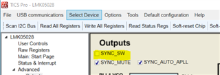
Can you advise me on how to configure ZDM using the TICSPRO.

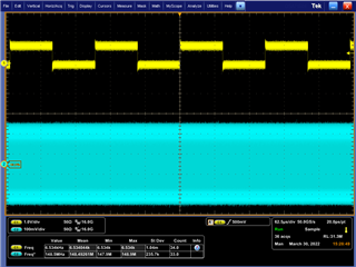
I want to use LMK05028 to generate 148.5 MHz video clock from a 67.5 kHz reference clock.

The ratio of input and output is 1:2200.

When I tried it using the TISPRo with the Configuration file attached,

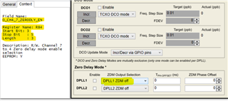
Register value for the feedback divider was different from my expectation as bellows:

  DPLL2_REF_FB_DIV_BY3-By0 (R502-505) weree 0x00, 0x00, 0x02, 0xDD

           ( =733d instead of 275d : 2200/8)

DPLL2_REF_NUM_BY4-By0 (R506-510) were 0x53, 0xfe, 0x60, 0x1f 0xd7)

         ( =360,749,998,039d instead of 0)

I appreciate it if you can let me know the procedure to configure the LMH05028 in ZDM using the TICSPRO

Can you also advise me on how to configure REF_DPLL mode as well.

Mita

temp1.tcs

  • Hello Mita,

    Is your DPLL2 locked? Are all of the following bits low?

    If they are not low, please press Update Frequency Plan and Run Script to recalculate the DPLL settings.

    Once you have your device locking properly, you can then configure the device for ZDM.

    To have the device operate in ZDM mode for the configuration you have provided, please follow these steps:

    1. Perform a soft-reset and ensure DPLL2 is locking.

    2. Enable ZDM for DPLL2.

    3. Select OUT0 for ZDM.

    4. Navigate to the Outputs page and toggle (turn on, then off) the SYNC_SW control.

    5. The input and output should now be synchronized.

    Regards,

    Kia Rahbar

  • Kia-san,


    Thank you for the answer.

    Please allow me to confirm my understanding and ask three more questions.

    1.  Configure the device in REF_DPLL mode.
    2.  Issue SOFT RESET
    3.  Wait until the DPLL is locked,
    4.  Enable ZDM mode
    5.  Select output port which is used for the feedback


    Q1. In REF DPLL mode, the feedback clock comes from the Pre-Divider.

        However, in ZDM, the feedback clock comes from the output divider.

        So, the feedback divider must be changed when the device is switched to ZDM.

        Does the TICSPRO automatically take care this change?


    Q2. For the DPLL2, the register “DPLL2_ZDM_CTRL0” may be mapped on

          address 262h (R610d. However, this address is marked as” RESERVED”

          on the “User's Guide SNAU233–April 2018 LMK05028 Register”.

          Is it typo?

         TICS pro may also access R0x1D1, but it is also marked as ” RESERVED”.


    Q3 . When you configure LMK05028 using the micro-controller which register do you need to

            Access to make the device in ZDM?


    Mita

  • Hello Mita,

    You are missing one step.

    1.  Configure the device in REF_DPLL mode.
    2.  Issue SOFT RESET
    3.  Wait until the DPLL is locked,
    4.  Enable ZDM mode
    5. Select output port which is used for the feedback
    6. Toggle (set high, and then set low) the SYNC_SW control

    Q1. Yes, TICS Pro automatically takes care of this change.

    Q2. It appears that the guide has not been updated to include the ZDM controls. DPLL2_ZDM_EN can be set on 262h bit 0 as you have stated, but 0x1D1 is not a register used for ZDM. Register 0x1D1 are DPLL loop filter settings that are reserved and should not be adjusted.

    Q3. To enabled ZDM for DPLL1, set R594[0] (DPLL1_ZDM_EN) high. To enabled ZDM for DPLL2, set R610[0] (DPLL2_ZDM_EN) high. R84[5:3] selects the output that will be ZDM for DPLL1. R84[2:0] selects the output that will be ZDM for DPLL2.

    Please note that if you hover (put your mouse over a control), you will be able to see the registers associated with that control on the left side of TICS Pro as I have shown below:

    Here is also a TICS Pro configuration I created in our lab:

    ZDM_LMK05028.tcs

    Please load this file and then toggle (set high, then set low) the SYNC_SW as shown:

    Once you have toggled the SYNC_SW, your input and output should be synced as shown below:

    Regards,

    Kia Rahbar

  • Kia-san,

    Thank you for the answers.

    Your answers have resolved all my questions.

    Mita.