This thread has been locked.

If you have a related question, please click the "Ask a related question" button in the top right corner. The newly created question will be automatically linked to this question.

CDCM6208: 322.265625 / 644.53125 MHz ref. clock generation for USXGMII

Part Number: CDCM6208
Other Parts Discussed in Thread: CDCE6214

Dear tech support,

I need to provide a 322.265625 MHz or 644.53125 MHz reference clock to an Intel Cyclone 10 GX FPGA for use with an USXGMII interface. This is needed to communicate with a 10GBASE-T PHY from Marvell.

I'd like to generate such ref. clock with a CDCM6208 V2, but I can't find any clear indication on how to calculate the jitter / phase noise when using the output fractional dividers.

I see that I can't obtain the required frequency with an integer divider.

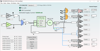
My Idea was to adopt the following configuration to obtain the desired clock. I see that the EVM software can plot the phase noise for integer divider outputs but not for fractional dividers ones.

I also need to generate other clocks, such as 100MHz, 50MHz and other aux ones which doesn't have strict jitter requirements.

Can you show me how to calculate the jitter in this case?

Is there any other TI clock generator more suitable for this application? I'd prefer a power supply of 1.8V if possible.

Thank you

  • Hi,

    While using CDCM6208 for required fractional output frequencies, its PFD frequency go very low and it will affect the jitter performance of the device.

    Instead to this I would be suggesting to have a look on the CDCE6214, which would have fractional PLL and can generate required frequencies with higher phase detector frequency. It has an option for 1.8V supply option also.

    Thanks!

    Regards,

    Ajeet Pal

  • Thank you,

    after some checks I decided to proceed with the CDCE6214 since it fits perfectly our application.

    I also need a 100 MHz clock output, which I thought to derive directly from the REFCLK after the x2 input multiplier (the green path in the following graph), using a 50MHz reference clock:

    The problem is that in TICS pro the connection is different. The MUX before the integer divider is not connected to the clock AFTER the x2 multiplier, but BEFORE. So I can't output 100MHz, but 50MHz, as the reference clock.

    Can you confirm that the datasheet is wrong and that I should follow the TICS configuration?

    Thank you

  • Hi,

    OUT0-4 can have an REF_CLK and PFD_CLK output options, where block diagram in datasheet shows generic diagram for reference output. 

    Table 9 in datasheet shows the register settings for REF_CLK or PFD_CLK at output channels.

    R25[9] selects the MUX for REF_CLK or PFD_CLK out.

    Thanks!

    Regards,

    Ajeet Pal

  • Hi,

    There would be one update on the PFD_CLK out, as ref multiplier operates in delay based circuit, it won't generate 50% duty cycle PFD clock. So your generated 100MHz out from PFD_CLK won't have 50% duty cycle output.

    Thanks!

    Regards,

    Ajeet Pal