This thread has been locked.

If you have a related question, please click the "Ask a related question" button in the top right corner. The newly created question will be automatically linked to this question.

LMK05028: LOFL/LOPL status won't clear when using 1pps (1Hz) input

Part Number: LMK05028

I'm using TICS Pro v1.7.4.1

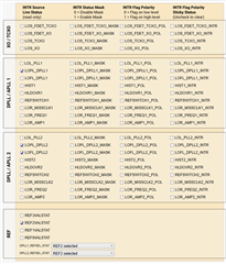
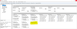
I can’t figure out how to avoid the LOFL/LOPL flags setting.  I have tried opening the window on those detectors drastically and the flags are still set.  I see that TICS reports what registers are written whenever I change a setting, so I check those regs in the regmap (converting from hex to dec because I guess it couldn’t be consistent) and find that all the frequency/phase lock regs it’s writing appear to be RESERVED in the register map.  With nearly no documentation on these regs and the feature I can’t figure out why these flags are still set.

Current config:

- 48MHz 10ppm XO
- 20MHz 10ppb TCXO
- TCXO doubler en on, MDIV = 1
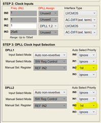
- 1pps at IN2 to DPLL 1,2, LVCMOS input
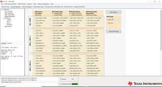
- OUT0-3: 10MHz from PLL2
- OUT4-7: 25MHz from PLL1
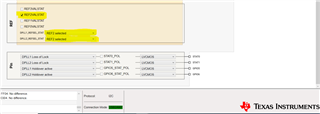
- DPLL clocks manual holdover, SW reg control, REF IN2
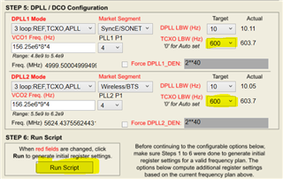
- DPLL modes 3 loop, SyncE/SONET, DPLL LBW=0.1, TCXO LBW=100
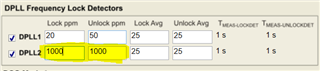
- DPLL1 freq lock ppm = 20, unlock ppm = 50, lock avg = 25, unlock avg = 25
- DPLL2 freq lock ppm = 80, unlock ppm = 100, lock avg = 100, unlock avg = 100 (trying large values on purpose)
- DPLL1 phase lock thresh = 13, unlock thresh = 25, LPF = 0 (set by script)
- DPLL2 phase lock thresh = 17, unlock thresh = 28, LPF = 0 (set by script)

TICS Pro main page

Other issues/bugs with the software:

  • DPLL BW must be less than 1 when using 1Hz input.  It would be great if the tool checked for this and produced a useful error rather than quietly failing.
  • Running the script enables the amplitude detection on all inputs. This should NOT happen with a 1Hz input, or ideally never be touched by the script.
  • I found that I also get another error where the script completely fails if one PLL is set in 3 loop mode and the other is set in 2 loop mode.  Doesn’t really affect me now, but seems like a bug in the tool.
  • Hello James,

    For your current device settings (1PPS input and DPLL LBW of 0.1), you will need to configure the TCXO LBW to be at least 600 Hz. Please try configure the TCXO LBW to this setting and then perform a run script for the DPLL settings to be updated for this new bandwidth. This should solve your locking issues.

    Thank you for the feedback! I will notify our software development team to correct these bugs.

    Regards,

    Kia Rahbar

  • I have now tried the TXCO LBW at 600Hz and all options above.  I am still seeing the flags set on the status page.  DPLL1 has LOPL set, and DPLL2 has LOPL and LOFL still set.  I have tried with both in holdover and with a 1pps input at IN2.

    TICS Pro status

  • Hello James,

    Please try the following process:

    1. Re-write all the register settings by pressing the Write All Registers button.

    2. Immediately after writing all the registers, press the Soft-Reset Chip button.

    3. Now readback the status bits.

    Please note it will take 10-60 seconds for the LOFL_DPLL to go low and may take a few to many minutes for the LOPL_DPLL to go low as it takes a significant amount of time for the device to lock to a small frequency such as a 1PPS signal.

    Regards,

    Kia Rahbar

  • OK I tried that, waited a few minutes, same flags are still set.

  • Hello James,

    Can you please provide a tcs file of your configuration? I will test it out after the weekend to see if I can determine the issue.

    Thanks!

    Regards,

    Kia Rahbar

  • Hello James,

    The issue with your configuration was that you had not set the priorities for the DPLL inputs, and therefore the DPLLs were not locking to the 1PPS input. For your configuration, you will need IN2 to be set to 1st priority for both DPLLs as shown below.

    I have made an updated configuration with this change and attached it below:

    1719-02_LMK05028_CMOS_CLK25MHZ_PPSIN2_TI_Working_V2.tcs

    I have also tested the configuration in our lab and was able to successfully see all the flags go low after a couple minutes and the references validate.

    Regards,

    Kia Rahbar

  • I tried the file and I see that LOPL Is cleared, but I also see that the config for the phase lock detectors is maxed out with the thresholds set to 63.  Should the phase lock detectors be open like this for 1pps?  Doing that does clear the LOPL flags on my configuration as well.  I'm still occasionally getting LOFL on DPLL2 only though.

  • Hello James,

    Yes, I set the phase lock detectors to their max values to speed up the time it takes for the DPLLs phase to lock to the 1PPS input.

    In regards to the LOFL, I will verify the configuration again to ensure I do not see the LOFL being set on my end and if it is, I will provide an updated configuration.

    Regards,

    Kia Rahbar

  • Hello James,

    Apologies for the delay.

    Attached below is a new configuration that will no longer result in the LOFL_DPLL2 flag to be set on.

    1719-02_LMK05028_CMOS_CLK25MHZ_PPSIN2_TI_Working_V4.tcs

    Please note that it will take a few minutes for the flags to go low.

    To solve the LOFL_DPLL2 flag issue, we bypassed the TCXO detect controls. The TCXO detect controls were resulting in the false trigger of the LOFL_DPLL2.

    Regards,

    Kia Rahbar

  • I'm still not getting those bits to clear.  I'll try another pps source on Monday.  The edges look clean on the source I'm using right now, but maybe there's some other issue.

  • Hello James,

    If the configuration I provided does not get the LOFL_DPLL2 flag to go low, please try the following:

    1. Load the configuration I provide.

    2. Updated the DPLL lock detect ppm to 1000 ppm.

    3. Perform a soft-reset chip

    4. Continously readback the status registers for a few minutes until all flags are low.

    Regards,

    Kia Rahbar

  • That seems to clear the flags now.  It leads back to an earlier question though - this seems to be opening the detection aperture for these flags which makes them less sensitive to any potential issues with synchronizing to the input.  Is that expected with a 1pps input?  What should be a reasonable threshold based on the component's capabilities?

  • Hello James,

    Yes, this is expected for a 1PPS input. Due to the long lock time required for locking to a 1PPS input, we typically recommend increasing the DPLL frequency lock detectors and phase lock detectors to allow for a faster lock time. This will not affect the performance of the device, but will rather widen the flag detector ranges for faster locking of the DPLLs. 

    As for the reasonable thresholds for a 1PPS input, the settings I have provided in the configuration are our typical recommendations (Frequency lock detect = 1000 ppm and phase lock detect = a setting of 63).

    Regards,

    Kia Rahbar 

  • OK thanks for the confirmation.  This looks to be a good configuration now.