This thread has been locked.

If you have a related question, please click the "Ask a related question" button in the top right corner. The newly created question will be automatically linked to this question.

LMX1204: Questions

Part Number: LMX1204

Hello team,

I have questions about LMX1204 below.

  • Can we use the device for 1:5 clock distribution up to 6GHz?
    I am not sure if LOGICLK output can be used same as CLKOUT0, 1, 2,3, so I am wondering if it can be used 1:5 distributor.
  • Can we set output buffer of these 5 outputs ON or OFF individually?
  • Do you have some evaluation data to show performance for channel to channel isolation?

Best regards,

  • Hi Sato-san,

    Can we use the device for 1:5 clock distribution up to 6GHz?
    I am not sure if LOGICLK output can be used same as CLKOUT0, 1, 2,3, so I am wondering if it can be used 1:5 distributor.

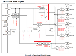
    LMX1204 has only 4 output channels (CLKout) for higher frequency out, where as Logic_clock can operate till 800MHz. Both clock outs using different dividers and can not have total 5 channel distribution including logic clock at high frequency (6GHz).

    Can we set output buffer of these 5 outputs ON or OFF individually?

    Yes, all output channels can be controlled (ON/OFF) individually. 

    Do you have some evaluation data to show performance for channel to channel isolation?

    Clock out channels will have same output frequency (can be buffer / multiplier / divider), hence this specs doesn't to needed.

    There can be if one channel is OFF and it sees the leakage output. Not performed, if needed can provide the data.

    Thanks!

    Regards,

    Ajeet Pal

  • Hello Ajeet-san,

    Thank you for your comments.

    Regarding isolation, I would like to know below. If it is very helpful if you could measure and provide the data.

    1. In case there is no clock input and all output buffers are ON, channel to channel signal transfer characteristics, for example CLK0 to CLK1.
      I would like to know how much leakage there will be on CLK1 when there is signal applied to CLK0 from externally.

    2. In case there is clock input and frequency characteristics when outputs are ON and when outputs are OFF.
      Especially, I would like to know how much leakage from clock input there will be on output when outputs are OFF.

    Best regards,

  • Hi Sato-san,

    In case there is no clock input and all output buffers are ON, channel to channel signal transfer characteristics, for example CLK0 to CLK1.
    I would like to know how much leakage there will be on CLK1 when there is signal applied to CLK0 from externally.

    I think, I am not getting this scenario correctly. When you have external input at CLK0, it may affect the device as it feeds external input at CLK0 pin, which will have reliability issue. Can you please elaborate this condition properly. 

    In case there is clock input and frequency characteristics when outputs are ON and when outputs are OFF.
    Especially, I would like to know how much leakage from clock input there will be on output when outputs are OFF.

    Input to output leakage should be in the range of around -50dBc and it may also depends on the operating frequency. The provided number is at 5GHz frequency.

    Thanks!

    Regards,

    Ajeet Pal  

  • Hello Ajeet-san,

    Thank you for your comments.

    I think, I am not getting this scenario correctly. When you have external input at CLK0, it may affect the device as it feeds external input at CLK0 pin, which will have reliability issue. Can you please elaborate this condition properly. 

    I will confirm again about condition. I will get back to you later.

    Input to output leakage should be in the range of around -50dBc and it may also depends on the operating frequency. The provided number is at 5GHz frequency.

    Do you have also leakage information at 6GHz frequency? It would be helpful actual measurement result or graph/plot data with some frequencies.

    Best regards,

  • Hi Sato-san,

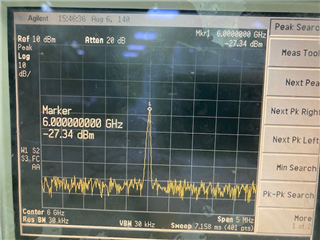
    Below are the measured data at 6GHz for input to output leakage,

    CLKout3 output enable; All clock out OFF

    CLKout3 output driver disable R4[bit3] --> 0; All clock out OFF

    CLKout3 channel disable R3[bit15] --> 0; All clock out OFF

    Here, the overall leakage from input to output after disabling the channel would be ~ -48.8dBc.

    Thanks!

    Regards,
    Ajeet Pal

  • Hello Ajeet-san,

    Thank you for the measurement data.

    In case there is no clock input and all output buffers are ON, channel to channel signal transfer characteristics, for example CLK0 to CLK1.
    I would like to know how much leakage there will be on CLK1 when there is signal applied to CLK0 from externally.

    I think, I am not getting this scenario correctly. When you have external input at CLK0, it may affect the device as it feeds external input at CLK0 pin, which will have reliability issue. Can you please elaborate this condition properly. 

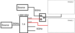
    In case leakage from external circuit may exist on output of LMX1204 like below case for example, I would like to know how it affects adjacent output. Do you have data for this performance?

    Best regards,

  • Hi Sato-san,

    LMX1204 has channel to channel leakage around -45dBc, this also may affect on the PCB layout, which could couple the output on board too.

    Based on above setup, CLK1 may have leakage (-45dBc + switch pin isolation) along with switch pin-pin leakage, which would be anyways better than channel to channel leakage. switch would have their own pin isolation.

    Thanks!

    Regards,

    Ajeet Pal

  • Hello Ajeet-san,

    Thank you very much for the information.

    Do you have any measurement data for this?

    Best regards,

  • Hi Sato-san,

    Yes, -45dBc is the measured data at 3GHz operating frequency and it would be almost same at 6GHz also.

    Below is the setup details:

                   Fundamental Freq: 3GHz

                   Source Power: 10dBm

                   Differential Input

                   Single Ended Output

                  Measurement : Clock Out1


    Device Condition

    Power [dBm]

    Default

    2.9

    Power Down

    -60.19

    Disable Clock Out Buffer

    -32.45

    PINOE=13  (Enable all output except clock1)

    -43.37

    PINOE=0 (Disable all output drivers)

    -52.5

    Thanks!

    Regards,

    Ajeet Pal