This thread has been locked.

If you have a related question, please click the "Ask a related question" button in the top right corner. The newly created question will be automatically linked to this question.

NE555N astable, operating point not found

Other Parts Discussed in Thread: TINA-TI, NE555, TLC555

Dear all,

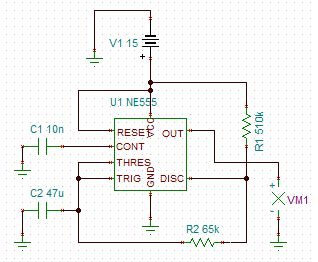
Kindly, attached is a basic NE555N astable multi-vibrator where the required times are:

OUTPUT HIGH: 2 sec.

OUTPUT LOW: 20 sec.

The problem is that I am receiving a message "operating point not found", and the other problem is that i need a switch SPDT within TINA-TI to be controlled by this timer. My TINA-TI version is Version 7.0.80.96 SF-TI.

Please help me with this problem.

Yours truly,

Mahir

1031.NE555.pdf

  • Hello Mahir,

    Your circuit as drawn will have a longer output high time than it will be low. This is opposite of your requirement.

    To correct this, I suggest. changing R1 to 60.4k and R2 to 619k then add a diode across R2 (cathode to C2 side).

    Now C2 will charge through R1 and new diode in 2 seconds while output is high and C2 will discharge  through R2 in 20 seconds while output is low.

    I do not have a answer about the Tina simulation, but changing the default settings for higher accuracy or longer settling time may help.

    Regards,
    Ron Michallick


  • Dear Mr. Ron,

    Thank you for your response...

    I made the changes on my cct as attached, but also the same problem "operating point not found", I reached the required cct using TLC555 but still wondering about the message appear with NE555.

    Hoping to solve this case.


    Best Regards 

    Mahir


  • Mahir,

    Send me your NE555 TI-Tina circuit.
    I will try to get it to simulate properly.

    Regards,
    Ron


  • Dear Ron,

    I am not sure why I can't upload the simulation file (.TSH) to the site!!! please help me with this.

    I solved this case with Mr. Marcos opinion (using voltage generator with general wave and by changing the peak values and the times) and this worked with the voltage-controlled switch, but using NE555 is important for further hardware implementation.

    Also, the use of TLC555 as attached, gives the same signal, but not working with the voltage-controlled switch, and this is not obvious for me!!!! 

    Hoping to receive your opinion about this.

    Regrads,

    Mahir


  • Mahir,

    I ran into the same problem. I solved it by using a different tool.

    Try: Analysis - Steady State Solver - MaxSearchTime = 60
    This is my only solution.

    Regards,
    Ron