This thread has been locked.

If you have a related question, please click the "Ask a related question" button in the top right corner. The newly created question will be automatically linked to this question.

CDCE925: Output wave form question

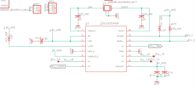
Part Number: CDCE925

Hello.

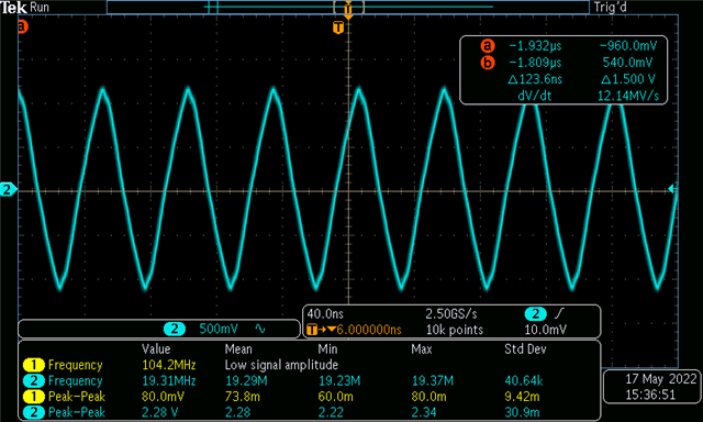
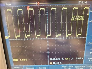
I was able to get the desired frequency output in pll, but the output wave resembles more of a triagnlish sine wave. I was expecting more of a square wave output.

Would there be a way to fix this problem?

My input crystal frequency is 16.00MHz, and output frequency is 19.3MHz

I used the TI-clock pro program to generate the each register bits, and I programmed it through I2C programming port.

Thanks a lot in advance

  • Hi Young,

    What is your scope setting? 1MΩ, DC couple, full bandwidth?

    Looks to me that you have a DC-blocking capacitor, what is the cap value?

  • I am using 1x probe, AC coupling, 1Mohm termination, and full bandwidth.

    The probe I am using is P6100 with 1x setting. I am not using any DC-Blocking capacitor.

    I also programed 10pf as a loading crystal capacitor in i2c programming

    thank you

    Young

  • Hi Young,

    I tested an EVM, the output is indeed square wave. How did you interface the clock output to other device? Could you disconnect the connection to other device so that you can measure real output from CDCE925?

  • I don't understand your question(How did you interface the clock output to other device?) I am just measuring straight out from the CDCE925

    I am getting the real output from CDCE925 from Y1, and Y5. and the output has nothing attached to it. I am just measuring the output pin from the CDCE925

    without anything. Could this be a crystal issue?

    Thank you very much

  • I have a question. The oscilloscope schematic roughly looks like this, and I think that this type of formation may cause huge RC constant. Does that mean that I can't probe the output with oscillsocpe?

    Thanks,

    Young

  • Hi Young,

    the 50pF are too big loading for the output driver of CDCE925. That will result in that sinewave signal that you are measuring. You will need to find a probe/scope with lower cap load. Something <10pF would be good.

    Typically Oscopes have a 50Ohm option too. That might have lower cap load. You can try to measure the signal with that. Note, you will see VDDout / 2 swing level as 50 Ohm is a ideal termination.

    Also one more note: Please measure not at the pin of CDCE925 but at the receiver or at the end of the PCB trace. Otherwise you will measure a lot of reflections.

    regards,

    Julian